

Method for correcting small wireframe transient electromagnet inductive effect through utilizing decay curve slopes
A transient electromagnetic and decay curve technology, applied in the field of geophysical exploration, can solve the problems of not participating in data processing, difficult to meet actual engineering, affecting the accuracy of mathematical interpretation of data, etc. blind spot effect
Active Publication Date: 2013-08-07
XIAN RES INST OF CHINA COAL TECH& ENG GROUP CORP
View PDF2 Cites 5 Cited by
- Summary
- Abstract
- Description
- Claims
- Application Information
AI Technical Summary
Problems solved by technology
Due to the limitation of underground construction space, this method cannot adopt the large emission line frame (generally with a side length greater than 100m) that is routinely used on the ground, and often uses multi-turn small loop lines with a side length less than 2m, which will cause bands in the original sampling data. The effects of wireframe self-inductance and mutual inductance that cannot be ignored make the measured small wireframe transient electromagnetic secondary field attenuation curve quite different from the ground large wireframe transient electromagnetic secondary field attenuation curve, which makes many more mature processing and The inversion method cannot be applied, which affects the accuracy of data mathematical interpretation and is difficult to meet the needs of actual engineering
[0003] At present, there is no technology to remove the influence of the inductance effect from the data. The general method is to directly delete the early affected data without participating in the data processing, so that there will be shallow blind spots in the interpretation results.
Method used
View moreImage
Smart ImageViewing Examples

Examples
Embodiment
[0066] t U U’
Login to View More PUM
 Abstract
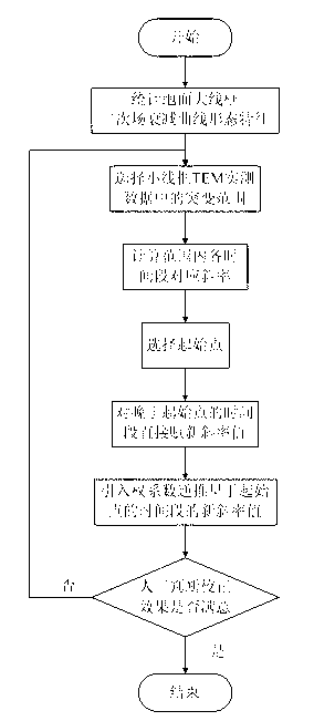
The invention relates to the technical field of geophysical exploration, and in particular to a method for correcting a small wireframe transient electromagnet inductive effect through utilizing decay curve slopes, which is used for correcting an inductive effect which is generated when small wireframe transient electromagnet uses a plurality of turns of small return wires to acquire data and eliminating the influence of the inductive effect in an existing small wireframe transient electromagnet processing process. The method adopts process steps of: (1) starting; (2) carrying out statistics on ground large wireframe secondary field decay curve morphological characteristics; (3) selecting a mutational range of small wireframe transverse electric and magnetic field (TEM) measured data; (4) calculating the corresponding slopes of all the time periods within the range; (5) selecting an initial point; (6) directly assigning new slope values for the time periods behind the initial point; (7) introducing a weight coefficient to inversely deduce the new slope values of the time periods before the initial point; and (8) artificially judging whether a correction effect is satisfied or not according to the slope variance yield (such as less than 0.3) of the curve of all the measured points, if yes, ending up, and if not, returning to the step (3).
Description
1. Technical field: [0001] The invention relates to the technical field of geophysical exploration, in particular to a method for correcting the transient electromagnetic inductance effect of a small wire frame by using the slope of an attenuation curve. 2. Background technology: [0002] The small wire frame transient electromagnetic method is an electromagnetic prospecting method that has been widely used in the fields of coal mine advanced prospecting, roof and floor water damage detection, side walls and internal water damage detection of working faces in recent years. Due to the limitation of underground construction space, this method cannot adopt the large emission line frame (generally with a side length greater than 100m) that is routinely used on the ground, and often uses multi-turn small loop lines with a side length less than 2m, which will cause bands in the original sampling data. The effects of wireframe self-inductance and mutual inductance that cannot be ig...
Claims
Login to View More Application Information
Patent Timeline
 IPC IPC(8): G01V3/38G01V3/30
Inventor范涛赵兆王继矿吴迪宁殿艳鲁晶津
OwnerXIAN RES INST OF CHINA COAL TECH& ENG GROUP CORP