Supercharge Your Innovation With Domain-Expert AI Agents!

Synchronous signal generating method and device of power line carrier communication system

A power line carrier and synchronization signal technology, applied in the direction of synchronization device, distribution line transmission system, transmission system, etc., can solve the problem that the synchronization signal cannot meet the accurate synchronization of the transmitter and the receiver, strong anti-noise, impedance mismatch multipath, The problem of large impedance transformation, etc., achieves the effects of good auto-correlation and cross-correlation performance, convenient and adjustable frequency range, and accurate synchronization of data symbols.

Active Publication Date: 2013-08-07
深圳市力合微电子股份有限公司
View PDF5 Cites 2 Cited by
  • Summary
  • Abstract
  • Description
  • Claims
  • Application Information

AI Technical Summary

Problems solved by technology

However, since the correlation of the repeated OFDM data is not strong, the synchronization accuracy of the generated synchronization signal is not high, and the noise resistance is not strong
In the power line carrier communication system, the power line channel is a very bad channel, with complex interference noise, large impedance transformation, large attenuation, serious interference, serious impedance mismatch and serious multipath fading.
Therefore, the synchronization signal generated by the above method cannot meet the requirements of accurate synchronization between the transmitting end and the receiving end and strong noise resistance during application.

Method used


Image

  • Synchronous signal generating method and device of power line carrier communication system
  • Synchronous signal generating method and device of power line carrier communication system
  • Synchronous signal generating method and device of power line carrier communication system

Examples


Embodiment Construction

[0025] The present invention will be described in further detail below in combination with specific embodiments and with reference to the accompanying drawings.

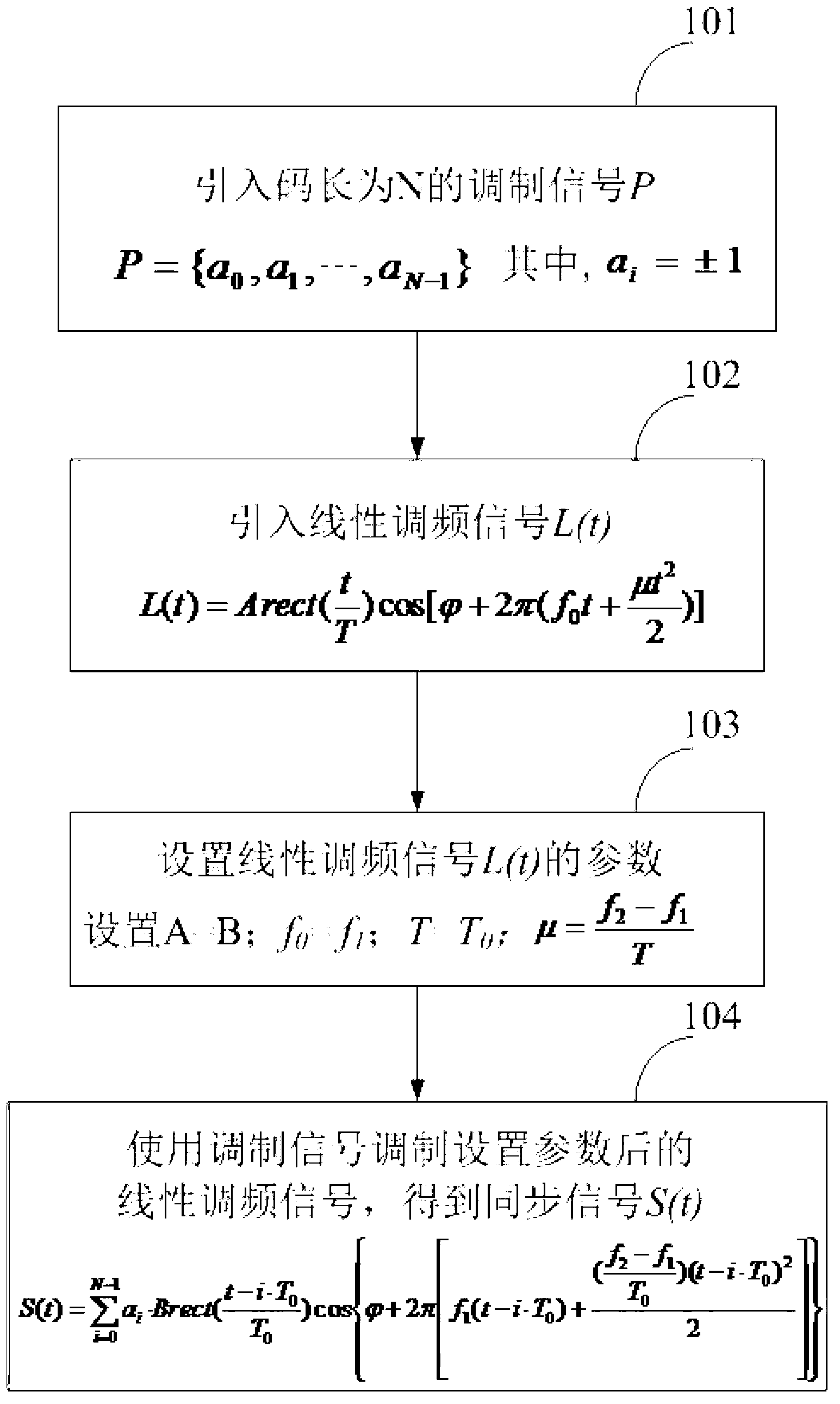
[0026] Such as figure 1 As shown, it is the synchronization signal generation method of the power line carrier communication system in this specific embodiment, which is used to generate the number of segments as N=7, the signal amplitude as B=1, and the modulation time of each segment signal as T 0 =128×10 -6 s, a synchronous signal with a frequency range of 10-50kHz (that is, f 1 =10kHz, f 2 =50kHz). The generation method includes the following steps:

[0027] Step 101), introduce the modulated signal P with code length N=7, P={a 0 ,a 1 ,B,a N-1}, where a i =±1. In this specific embodiment, the length of the synchronous signal to be generated is 7, that is, the length of the selected modulation signal is also 7. In this specific embodiment, the Barker code is used as the modulation signal, P={+1,+1,+1,-1 ...


PUM


Abstract

The invention discloses synchronous signal generating method and device of a power line carrier communication system. Frequency-modulated chirp signals L(t) are modulated to obtain synchronous signals by means of modulation signals of expression P, and since the modulation signals of the expression P are good in correlation performance and the frequency-modulated chirp signals are also good in self-correlation and mutual-correlation performance, the generated synchronous signals are good in correlation, namely accurate and reliable position is provided for synchronous timing. On the other hand, the frequency-modulated chirp signals are similar to general sinusoidal signals and have constant envelope amplitude, so that the synchronous signals generated have constant envelope amplitude too and are high in noise resistance. Furthermore, in the synchronous signal generating method, frequency range of the synchronous signals is related to parameter setting of the frequency-modulated chirp signals, and synchronous signals in which kind of frequency ranges can be generated by setting parameters of the frequency-modulated chirp signals, so that frequency ranges of the synchronous signals are convenient to adjust.

Description

【Technical field】 [0001] The present invention relates to a power line carrier communication system, in particular to a method and device for generating a synchronous signal of the power line carrier communication system. 【Background technique】 [0002] Power line carrier communication technology, referred to as PLC, refers to a communication method that uses power lines to transmit data. It can make full use of the existing power distribution network infrastructure and provide users with data communication services without any wiring. The power line carrier communication system is a burst communication system, which has very strict requirements on synchronization performance. Any error in time or frequency will cause a great loss to the performance of the power line carrier communication system. Therefore, it is of great significance to the power line carrier communication system to properly design the synchronization signal so that the transmitting end and the receiving e...

Claims


Application Information

Patent Timeline
IPC IPC(8): H04L7/00H04B3/54
Inventor 不公告发明人
Owner 深圳市力合微电子股份有限公司
Features
  • R&D
  • Intellectual Property
  • Life Sciences
  • Materials
  • Tech Scout
  • Unparalleled Data Quality
  • Higher Quality Content
  • 60% Fewer Hallucinations
Learn More