Metal spinning cutter

A technology for machining knives and knives, used in forming tools, manufacturing tools, metal processing equipment, etc., can solve the problem of poor workpiece hole roughness, slow processing efficiency, unsuitable for processing pistol bolts and muzzle caps. problem, to achieve the effect of simple operation and easy implementation

Inactive Publication Date: 2013-08-14
CHONGQING JIANSHE IND GRP
View PDF8 Cites 0 Cited by
  • Summary
  • Abstract
  • Description
  • Claims
  • Application Information

AI Technical Summary

Problems solved by technology

If the conventional turning and boring processing is carried out by using tools such as turning tools, the processing efficiency will be slow, and the roughness of the processed workpiece holes will be poor, which will restrict the processing progress.
[0003] Therefore, the traditional processing tool is not suitable for processing the pistol with the combination of the gun bolt and the muzzle cap.

Method used


Image

  • Metal spinning cutter
  • Metal spinning cutter
  • Metal spinning cutter

Examples


Embodiment Construction

[0016] Specific embodiments of the present invention will be described below in conjunction with the accompanying drawings.

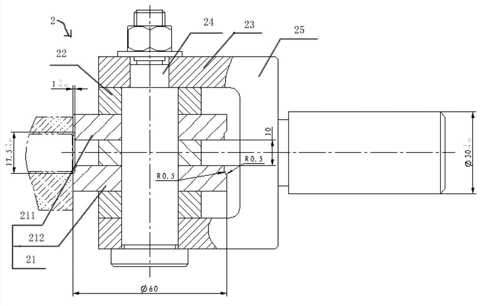
[0017] In the present invention, in the spinning process, two different blades need to be used together to carry out the spinning process on the workpiece, which will be referred to as the spinning angle tool 1 and the spinning tool 2 respectively.

[0018] The spinning angle tool 1 and the spinning tool 2 of the spinning tool of the present invention are introduced.

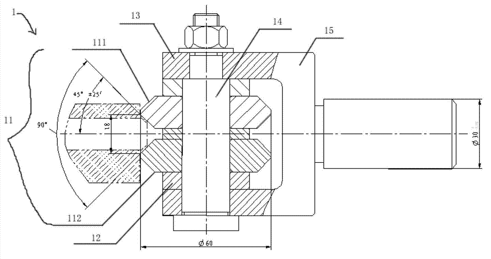
[0019] figure 1 It is a structural schematic diagram of the tool used for spinning angle in the present invention. Such as figure 1 As shown, the tool 1 used for spinning the muzzle into a certain angle spinning angle includes a tool holder 15, a mandrel 14, a middle gasket 13, gaskets 12 at both ends and a blade 11. Wherein the two ends of the blade 11 are in the shape of an inverted triangle, and the apex angle of the ends is about 45°. In order to make the force uniform and easy to...


PUM


Abstract

The invention provides a metal spinning cutter. The metal spinning cutter is used for performing metal spinning for a firearm part with two small end holes, a middle large hole and a thin end. The metal spinning cutter is characterized by comprising a cutter saddle, a mandrel, a middle washer, two end washers and a blade, wherein the blade is limited in the middle of the mandrel by the two end washers, the two end washers are symmetrical with each other relative to the center line of a cylinder, which is connected with a tailstock of a lathe, of the cutter saddle, and the mandrel is connected onto the cutter saddle by nuts. The metal spinning cutter has the advantages that a muzzle can be machined by the metal spinning cutter, chipless metal spinning can be carried out according to plastic deformation of metal, metal spinning can be completed only by means of rotating a firearm bolt, and the metal spinning cutter is simple in operation and can be implemented easily.

Description

technical field [0001] The invention relates to a cutting tool, in particular to a spinning cutting tool which can be used to solve the problem of the small hole at the two ends and the large hole in the middle, and the spinning processing of a thin firearms part at one end. Background technique [0002] The previous pistol bolt and muzzle cap are two separate parts, which can be easily processed with a turning tool. At present, there is a pistol in which the bolt action and the muzzle cap are combined into one. In the bolt action, two small holes are formed, and the inner cavity structure of the middle large hole is formed. This pistol structure cannot be drilled or hinged. And the inner cavity is deep, and the aspect ratio reaches 6. If the conventional turning and boring process is carried out by using tools such as turning tools, the processing efficiency will be slow, and the roughness of the processed workpiece hole will be poor, which will restrict the processing pro...

Claims


Application Information

Patent Timeline
Patent Type & Authority Applications(China)
IPC IPC(8): B21D37/00B21D22/14
Inventor 陈光勇
Owner CHONGQING JIANSHE IND GRP
Why Eureka
Try Eureka