
Fin groove processing device

A technology of groove processing and fin placement molds, which is applied in positioning devices, metal processing equipment, metal processing machinery parts, etc., can solve the problems of relatively high welding technical requirements and unqualified macroscopic metallographic inspection samples, etc., to achieve Low welding technology requirements, improved welding processability, and the effect of increasing connection strength

Active Publication Date: 2016-01-20
SHANGHAI BAOYE GRP CORP
View PDF7 Cites 0 Cited by
  • Summary
  • Abstract
  • Description
  • Claims
  • Application Information

AI Technical Summary

Problems solved by technology

[0002] When the heating surface tube of a traditional hood type waste heat boiler is welded to the fins, the fins generally do not undergo groove processing, and the penetration depth of CO2 gas shielded welding is small. For the fins without grooves, the welding technical requirements Relatively high, and it is prone to unqualified macroscopic metallographic inspection samples

Method used


Image

  • Fin groove processing device
  • Fin groove processing device

Examples


Embodiment Construction

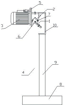
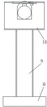
[0010] like figure 1 , figure 2 Shown: a fin groove processing device, which includes a fin placement mold 1, an adjustment plate 2, a motor 3, a bracket 4, a connecting plate 5, a baffle plate 6 and a milling power head 7, the bracket includes a flat plate 8, The vertical plate 9 and the channel steel 10, the vertical plate 9 is vertically arranged on the upper part of the flat plate 8, the upper part of the vertical plate 9 is connected to one side of the channel steel 10, and the front part of the channel steel 10 is connected with the milling power head 7, the connecting plate 5 and the motor 3 in sequence , one side of the milling power head 7 is connected with an adjustment plate 2, the adjustment plate 2 is circular and has a V-shaped notch, the notch faces outward, and the notch is connected to the side of the channel steel 10 with a fin to place the mold 1, and the notch is close to the One side of the connecting plate 5 is connected with a baffle plate 6, and the m...


PUM


Abstract

The invention relates to a fin slope machining device. The device comprises a fin placing mold, a regulating plate, a motor, a support, a connecting plate, a baffle plate and a milling power head, wherein the support comprises a flat plate, a vertical plate and channel steel, the vertical plate is vertically arranged at the upper part of the flat plate, the upper part of the vertical plate is connected with one side of the channel steel, the milling power head, the connecting plate and the motor are sequentially connected to the front part of the channel steel, the round regulating plate is connected to one side of the milling power head and is provided with an outward V-shaped notch, one side of the notch is connected with the fin placing mold, the other side of the notch is connected with the baffle plate, the fin placing mold is a flat plate, and a groove is transversely formed in the flat plate. The device provided by the invention is convenient to use, high in practicability, low in cost, safe, accurate and reliable.

Description

technical field [0001] The invention relates to a groove processing device, in particular to a fin groove processing device. Background technique [0002] When the heating surface tube of a traditional hood type waste heat boiler is welded to the fins, the fins generally do not undergo groove processing, and the penetration depth of CO2 gas shielded welding is small. For the fins without grooves, the welding technical requirements Relatively high, and it is prone to unqualified macroscopic metallographic examination samples. Contents of the invention [0003] The invention aims to overcome the defects of the prior art, and provides a fin groove processing device, which has a simple structure, is easy to manufacture, and has a simple process. [0004] In order to solve the problems of the technologies described above, the present invention is achieved in that: [0005] A fin groove processing device is characterized in that it includes a fin placement mold, an adjustment ...

Claims


Application Information

Patent Timeline
Patent Type & Authority Patents(China)
IPC IPC(8): B23C3/12B23Q3/00
Inventor 张东华赵增富蔡巧根吴小庆韩宇
Owner SHANGHAI BAOYE GRP CORP
Learn More