Laser welding clamp of sealed relay

A laser welding fixture and relay technology, applied in laser welding equipment, welding equipment, welding equipment, etc., can solve the problems of high cost, high labor intensity, low efficiency, etc., and achieve the goal of reducing disassembly, improving work efficiency, and reducing production costs Effect

Active Publication Date: 2013-08-14
GUIZHOU TIANYI ELECTRICAL
View PDF5 Cites 4 Cited by
  • Summary
  • Abstract
  • Description
  • Claims
  • Application Information

AI Technical Summary

Problems solved by technology

[0003] The object of the present invention is to provide a laser welding jig for sealed relays to solve the problem that traditional welding jigs need to be specially made corresponding to relays of different types and sizes. During production, it is necessary to replace the jigs and adjust the welding machine many times, resulting in high cost and labor intensity. Big, inefficient problem

Method used


Image

  • Laser welding clamp of sealed relay
  • Laser welding clamp of sealed relay

Examples


Embodiment

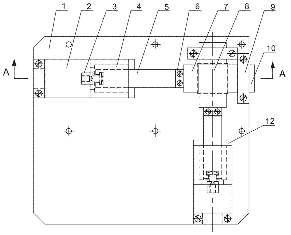
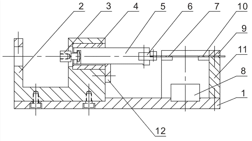
[0021] Embodiment: When the sealing cover needs to be welded on the sealed relay, select the matching sliding pressure plate 7 and the positioning pressure plate 10, and install them on the transfer block 6 and the support plate 11 respectively, and then fix them with screws, start the cylinder to pull the slider 5. Move to the hollow part in the support 2, so that the distance between the sliding platen 7 and the positioning platen 10 increases until the distance is greater than the size of the product to be clamped, then brake, and place the cover and the sealing relay on the pad On the block 8, after adjusting the position, tighten the screw on the positioning pressure plate 10 to complete the positioning; start the cylinder again, push the slider 5 to slide towards the support plate 11, until the sliding pressure plate 7 at the end of the slider 5 moves to the designated position and then closes Cylinder, tighten the screw on the sliding pressure plate 7, namely finish the ...


PUM


Abstract

The invention discloses a laser welding clamp of a sealed relay, the laser welding jig comprises a base plate, cushion blocks, and two groups of positioning mechanisms and clamping mechanisms which are respectively vertical to each other. The cushion block is mounted on the base plate and arranged between the positioning mechanisms and the clamping mechanisms. Changeable positioning press plates, sliding press plates and a large-stroke pneumatic clamping are adopted to position and clamp the sealed relays in different shapes and sizes, so that the problem about waste time and energy for entirely dismounting the laser welding clamp is avoided, tool cost is reduced, times for dismounting and mounting the clamp and adjusting welders are reduced, working efficiency is improved, and production cost is reduced.

Description

technical field [0001] The invention relates to a welding jig, in particular to a laser welding jig for a sealed relay. Background technique [0002] One process in the assembly process of the sealed relay is the laser welding of the cover. With the increase in the number of sealed relay products, different sizes and types of sealed relays need to be fixed with different welding fixtures when welding the cover. The traditional cover The welding fixture is a special fixture specially designed and manufactured for various types of products, and the manufacturing cost is very high; it must be replaced according to the welded relay when used. If the production process involves welding of several relays of different sizes, it needs to be completed every A new fixture is replaced after a relay, which increases the labor intensity and reduces production efficiency; and after each fixture is disassembled and installed, the program of the welding machine needs to be readjusted; in su...

Claims


Application Information

Patent Timeline
Patent Type & Authority Applications(China)
IPC IPC(8): B23K26/42B23K37/04B23K26/70
Inventor 张玉玲欧德超濮惠锦
Owner GUIZHOU TIANYI ELECTRICAL
Why Eureka
Try Eureka