
Cooling water spraying device of cutting machine

A water spray device and cutting machine technology, which is applied in grinding/polishing safety devices, metal processing equipment, grinding/polishing equipment, etc., can solve problems such as heat can not be eliminated in time, cutting machine blade wear, production yield reduction and other problems , to achieve the effect of more adjustable degrees of freedom, improved effective life, and improved surface quality

Inactive Publication Date: 2013-08-14
JIANGSU JCA ELECTRONICS TECH CO LTD
View PDF0 Cites 1 Cited by
  • Summary
  • Abstract
  • Description
  • Claims
  • Application Information

AI Technical Summary

Problems solved by technology

[0003] During the cutting process, since semiconductor materials are mostly brittle and hard, different cooling water adjustments need to be made according to different cutting processes. Although the cooling water spray device of traditional equipment has the function of drainage, due to the operating environment of the cutting machine and the characteristics of high-speed movement Requirements, the flow cannot be accurately drained to the effective cooling area, resulting in improper cooling and the heat generated when the device or material is cut cannot be eliminated in time, the blade of the cutting machine will wear abnormally, and the surface of the material to be cut will produce large edges or cracks. The yield rate is greatly reduced, resulting in serious economic losses

Method used


Image

  • Cooling water spraying device of cutting machine
  • Cooling water spraying device of cutting machine
  • Cooling water spraying device of cutting machine

Examples


Embodiment Construction

[0029] The specific implementation manners of the present invention will be further described below in conjunction with the drawings and examples. The following examples are only used to illustrate the technical solution of the present invention more clearly, but not to limit the protection scope of the present invention.

[0030] The technical scheme of concrete implementation of the present invention is:

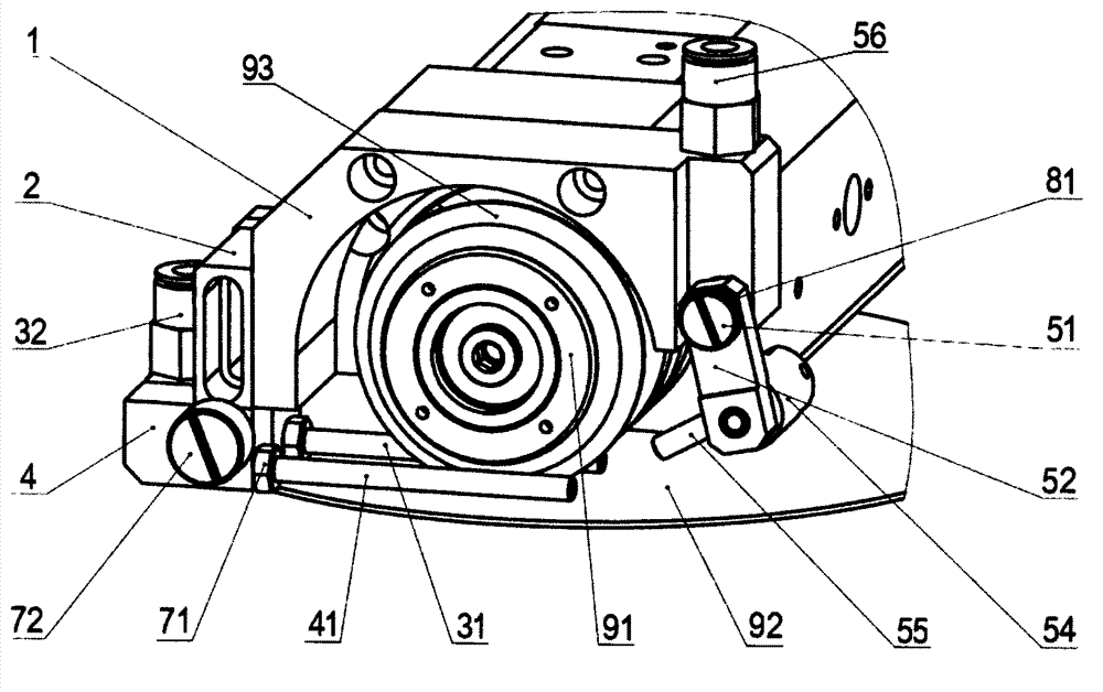
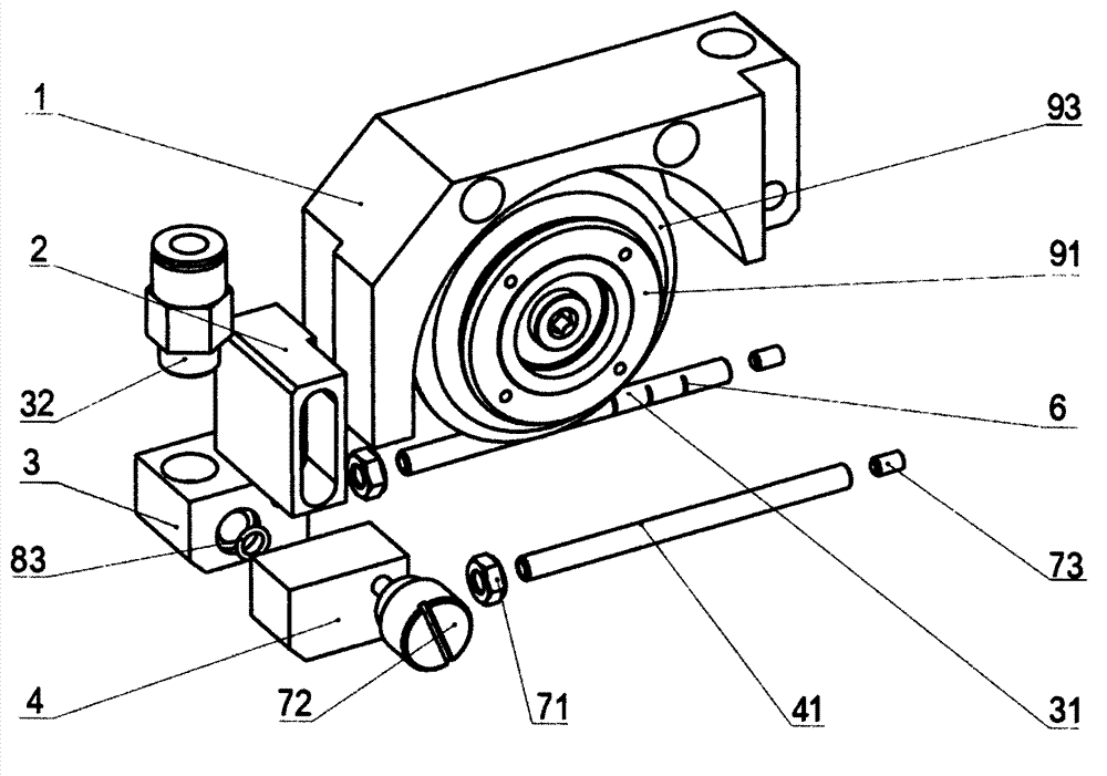
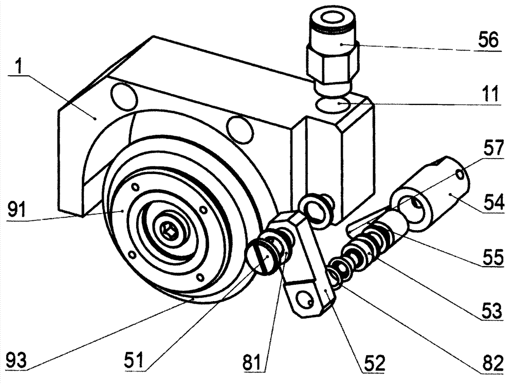
[0031] Such as figure 1 , figure 2 and image 3 As shown, the present invention provides a cutting machine cooling water spray device, including a fixed frame 1, a first spray bar 31, a second spray bar 41 and a third spray bar 55;

[0032] The fixed frame 1 is fixed with a height adjustment block 2 that can move up and down in translation, and the height adjustment block 2 is fixed with a first fixed block 3 and a second fixed block 4; the first fixed block 3 is screwed with the first spray rod 31, and the second fixed block The block 4 is threadedly connected with t...


PUM


Abstract

The invention discloses a cooling water spraying device of a cutting machine. The cooling water spraying device comprises a fixing frame, a first spray rod, a second spray rod and a third spray rod. A height adjusting block is fixed to the fixing frame, and a first fixed block and a second fixed block are fixed to the height adjusting block; the first spray rod is communicated with a first quick-plug connector via a first cavity; the second spray rod is communicated with the first quick-plug connector via a second cavity and the first cavity; a connecting rod is connected with the fixing frame by a locking screw, a rotary rod is fixed to an end of the connecting rod, a sleeve is sleeved on the rotary rod, and the third spray rod is arranged on the outer wall of the sleeve; the first spray rod and the second spray rod are respectively axially provided with a plurality of nozzles; the third spray rod is communicated with a second quick-plug connector via a fifth cavity, a fourth cavity, a communication hole and a third cavity sequentially; and a nozzle is arranged on the end surface, which is far away from the sleeve, of the third spray rod. The cooling water spraying device has the advantages that heat generated by a blade and a cut material in a cutting procedure can be effectively reduced, cuttings generated in the cutting procedure can be quickly cleaned under the impact action of a water flow, abrasion of the cutting blade is reduced, and the surface cutting quality of a device or the material is improved.

Description

technical field [0001] The invention relates to a cooling water spraying device, in particular to a cutting machine cooling water spraying device. Background technique [0002] The cutting machine is a key equipment for semiconductor post-packaging, and its function is to divide the device into individual circuit units. The working mechanism of the cutting machine is the powerful grinding of the grinding wheel blade. During the cutting process, the grinding wheel blade and the processed device will generate a lot of heat. However, excessive temperature will seriously affect the cutting quality and greatly shorten the service life of the tool. In order to control the temperature during scribing, it is necessary to cool the working area with cooling water. [0003] During the cutting process, since semiconductor materials are mostly brittle and hard, different cooling water adjustments need to be made according to different cutting processes. Although the cooling water spray ...

Claims


Application Information

Patent Timeline
Patent Type & Authority Applications(China)
IPC IPC(8): B24B55/02
Inventor 胡章坤杨云龙高阳高金龙
Owner JIANGSU JCA ELECTRONICS TECH CO LTD
Learn More