
Brake energy recovery system with pedal travel simulator, and control method of brake energy recovery system

A technology of braking energy recovery and pedal stroke, which is applied in the direction of brakes and pipeline layout, can solve problems such as inconsistent pedal feeling, achieve the effects of ensuring braking feeling, improving energy utilization rate, and simple hardware modification scheme

Inactive Publication Date: 2013-08-14
JILIN UNIV
View PDF13 Cites 32 Cited by
  • Summary
  • Abstract
  • Description
  • Claims
  • Application Information

AI Technical Summary

Problems solved by technology

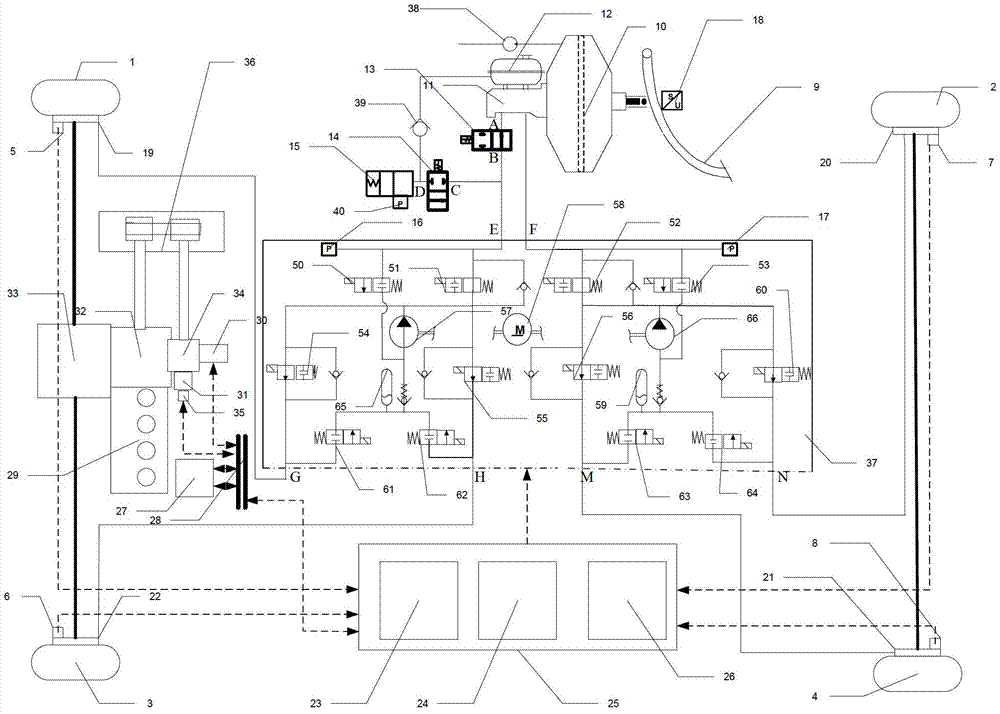
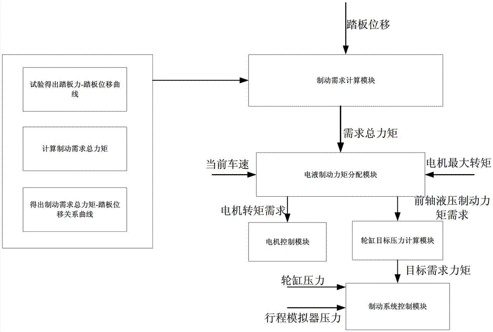
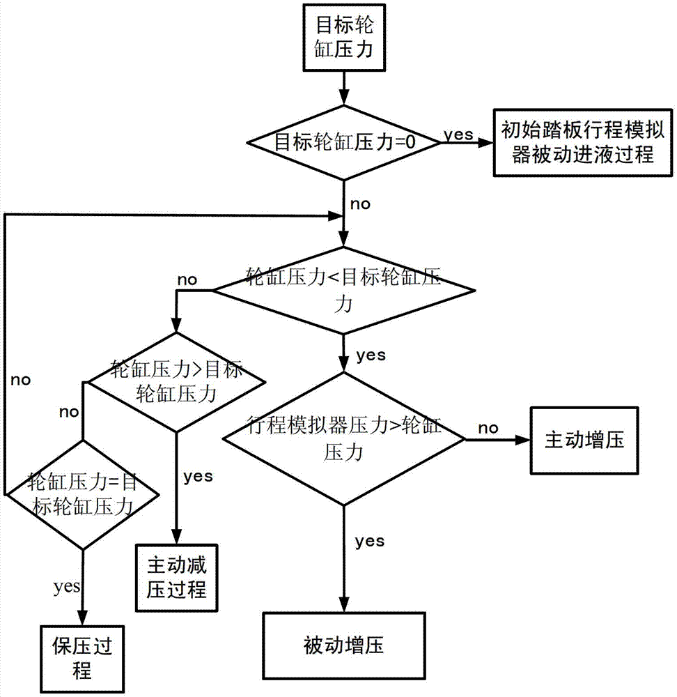
[0008] The technical problem to be solved by the present invention is to overcome the problem that the pedal feeling is inconsistent with that of traditional vehicles when the braking energy recovery system of electric vehicles and pure electric vehicles recovers energy, and to provide a braking energy recovery system with a pedal stroke simulator and its control method

Method used


Image

  • Brake energy recovery system with pedal travel simulator, and control method of brake energy recovery system
  • Brake energy recovery system with pedal travel simulator, and control method of brake energy recovery system
  • Brake energy recovery system with pedal travel simulator, and control method of brake energy recovery system

Examples


Embodiment Construction

[0037] The present invention is described in detail below in conjunction with accompanying drawing:

[0038] refer to figure 1 , The object of the present invention is to solve the problem that the pedal feeling cannot be coordinated in the regenerative braking of the current hybrid axle vehicle, and proposes a braking energy recovery system and its corresponding control method. figure 1 Shown in is the brake energy recovery system for a front-wheel drive parallel hybrid car with regenerative braking only at the front axle. The technical solution of the invention is also applicable to other hybrid vehicles and pure electric vehicles with H-shaped brake pipeline distribution.

[0039] refer to figure 1 , The braking energy recovery system with a pedal stroke simulator of the present invention includes a hydraulic braking subsystem, a regenerative braking subsystem and a braking control subsystem (BCS).

[0040] The hydraulic braking subsystem includes (ESP) hydraulic adju...


PUM


Abstract

The invention discloses a brake energy recovery system with a pedal travel simulator, and a control method of the brake energy recovery system and aims to solve the problem that pedals are felt different from conventional vehicles when brake energy recovery systems of electric and blade electric vehicles recover energy. A hydraulic brake subsystem comprises a brake pedal, a vacuum booster, a main brake cylinder, a liquid storage cup, a normally-open electromagnetic valve, a normally-closed electromagnetic valve, the pedal travel simulator, a hydraulic adjusting unit, a vacuum pump and a one-way valve. The vacuum pump is connected with the vacuum booster, the pedal travel simulator is connected with the liquid storage cup through the one-way valve, the upper end of the brake pedal is in ball joint riveting with the vacuum booster, the main brake cylinder is connected with the liquid storage cup,, a front cavity of the main brake cylinder is connected with an A port of the normally-open electromagnetic valve, a port B of the normally-open electromagnetic valve is connected with a port C of the normally-closed electromagnetic valve and a port E of the hydraulic adjusting unit, a port D of the normally-closed electromagnetic valve is connected with the pedal travel simulator, and a rear cavity of the main brake cylinder is connected with a port F of the hydraulic adjusting unit. The invention further provides the control method of the brake energy recovery system.

Description

technical field [0001] The invention relates to a braking energy recovery system for a hybrid electric vehicle and a pure electric vehicle, more precisely, the invention relates to a braking energy recovery system with a pedal stroke simulator and a control method thereof. Background technique [0002] The regenerative braking system is one of the most important links in hybrid electric vehicles and pure electric vehicles. In the braking process, it is necessary to reasonably distribute the regenerative braking force on the basis of ensuring the braking feeling, and accurately control the braking force. However, the original braking system cannot guarantee the pedal feel during the regenerative braking process, and for domestic automakers, it is difficult to fully develop a new braking system to meet the needs of regenerative braking due to the relative lack of component resources and technology accumulation. Therefore, it is of practical significance to develop an independ...

Claims


Application Information

Patent Timeline
Patent Type & Authority Applications(China)
IPC IPC(8): B60T8/17B60T17/04B60L7/10
Inventor 初亮杨毅姚亮王彦波马其贞祁富伟蔡健伟武同波杜圣荣张永生
Owner JILIN UNIV
Learn More