Eureka AIR delivers breakthrough ideas for toughest innovation challenges, trusted by R&D personnel around the world.

Collision-type respiratory zone air supply system

An air supply system and percussion-type technology, which is applied in mine/tunnel ventilation, mining equipment, earthwork drilling and mining, etc., can solve the problems of difficult implementation, large amount of secondary excavation, and large occupied space, so as to reduce tunnel opening The effect of excavating volume, ensuring fresh air demand, and reducing construction difficulty

Active Publication Date: 2013-08-14
XI'AN UNIVERSITY OF ARCHITECTURE AND TECHNOLOGY
View PDF10 Cites 0 Cited by
  • Summary
  • Abstract
  • Description
  • Claims
  • Application Information

AI Technical Summary

Problems solved by technology

This will lead to two problems: First, although the average concentration in the tunnel as a whole has decreased, due to the continuous release of smoke from the fire source, this part of the smoke cannot be completely eliminated, which will result in still relatively high concentrations of smoke in the tunnel. high concentration of smoke
Second, although the average concentration in the overall tunnel has decreased, there is still a relatively high concentration of fire smoke locally, which will lead to tunnel blockage, reduced visibility and other hazards
In this way, when the tunnel is excavated, it is necessary to reserve or re-excavate the upper and lower spaces of the tunnel at the same time, which occupies a large space and the amount of secondary excavation is too large, resulting in difficulties in implementation.

Method used


Image

  • Collision-type respiratory zone air supply system
  • Collision-type respiratory zone air supply system
  • Collision-type respiratory zone air supply system

Examples


Embodiment

[0045] Specific embodiments of the present invention are provided below, and it should be noted that the present invention is not limited to the following specific embodiments, and all equivalent transformations done on the basis of the technical solutions of the present application all fall within the scope of protection of the present invention.

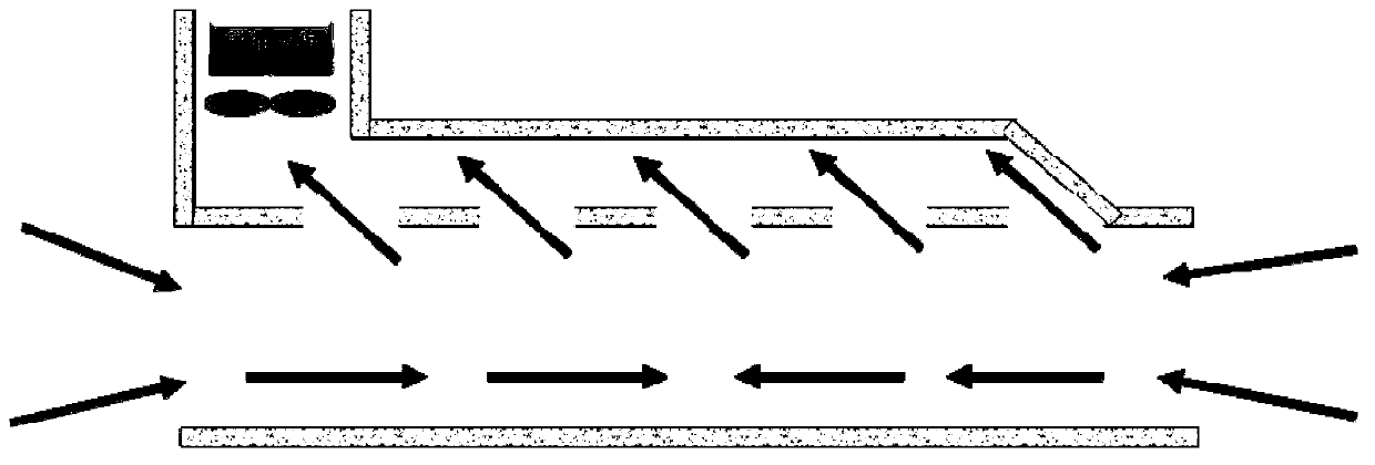
[0046] Comply with the above technical solutions, such as Figure 7 , Figure 8 As shown, the top plate height of the ∏-shaped smoke baffle wall is 2m, and the distance between the lower end of the Π-shaped smoke baffle wall and the static pressure box is 1.5m; the width of the Π-shaped smoke baffle wall is 0.5m . The cross-sectional size of the ∏-shaped smoke baffle wall 1 is 0.5m×0.5m. The cross-sectional dimension of the static pressure box 5 is 2m×1m; the width of the second nozzle 2 and the first nozzle 3 is 0.3m, and the distance between the two is 0.5m; the cross-sectional dimension of the air supply duct 4 is 0.5m× 0.5m....


PUM


Abstract

The invention discloses a collision-type respiratory zone air supply system which comprises a U-shaped smoke-blocking vertical wall, an air supply pipe and a static box. The U-shaped smoke-blocking vertical wall comprises a top plate and two side plates which are perpendicular to the top plate and which are symmetrically fixed below the top plate. The top plate and the two side plates form a semi-closed space with a downward opening. The U-shaped smoke-blocking vertical wall is fixedly suspended in a channel. The static box corresponds to the U-shaped smoke-blocking vertical wall and is disposed at the bottom of the channel. The static box is connected with the air supply pipe which is connected with a fan. The upper end of the static box is provided with a second spout and a first spout. The spouts are symmetrically disposed in relation to the U-shaped smoke-blocking vertical wall. Outgoing air from the first spout and outgoing air from the second spout form an included angle and intersect at the lower end of the U-shaped smoke-blocking vertical wall. Both the first and second spouts supply air at the speed of 0.5m / s. The collision-type respiratory zone air supply system guarantees an effective escape channel to be formed in the channel, only the static box is required to be set at a corner of the channel, and excavated volume of the channel is reduced evidently.

Description

technical field [0001] The invention relates to a tunnel fire ventilation system, in particular to an air supply system for an impingement breathing zone. Background technique [0002] Tunnels are the product of the rapid development of modern cities. Since the second half of the 20th century, the urban areas of various countries have gradually expanded, and the urbanization development process has gradually accelerated. This accelerated urbanization process has led to the need for urban traffic with a large transportation volume, fast speed, low energy consumption, low pollution, and occupation. Urban transportation with a small footprint. Tunnel Jiangxi Copper was conceived and born during this period. As an advanced means of transportation, tunnel has incomparable advantages compared with traditional transportation methods. However, with the development of tunnel traffic, vicious accidents such as tunnel fires occur frequently, often causing serious casualties and prop...

Claims


Application Information

Patent Timeline
Patent Type & Authority Applications(China)
IPC IPC(8): E21F1/00
Inventor 高然李安桂张莹罗娜
Owner XI'AN UNIVERSITY OF ARCHITECTURE AND TECHNOLOGY
Why Eureka
Eureka Blog
Learn More