Rock-soil pressure sensor embedding device and embedding method thereof

A technology of earth pressure sensor and pressure sensor, which is applied in the field of geotechnical engineering, can solve the problems of low quality of protective layer, low embedding efficiency, and large size of protective layer, so as to reduce the size of sensor protective layer, cushion size and excavation The effect of reducing the amount and improving the quality of the protective layer

Active Publication Date: 2014-05-21
JSTI GRP CO LTD
View PDF6 Cites 16 Cited by
  • Summary
  • Abstract
  • Description
  • Claims
  • Application Information

AI Technical Summary

Problems solved by technology

[0011] 1. It is necessary to dig a pit with a diameter of about 1.2m, and a large amount of cushion material and original medium soil are required to be backfilled. The quality of the backfill cannot be effectively controlled, which will disturb the original medium and change the physical and mechanical properties of the original medium soil.
[0012] 2. The size of the protective layer above the sensor is too large, and the quality of the protective layer is not high, changing the stress around the sensor, so that the measured data cannot represent the nature of the original medium itself;
[0013] 3. The burial efficiency is low, the excavation volume is large, and the installation and configuration require a lot of manpower and material resources;
[0014] 4. The validity of the sensor measurement is not guaranteed
When the earth pressure cell is buried in the coarse-grained soil and rock, the large particles may cause local stress concentration on the sensitive surface of the sensor, which affects the accuracy of the measurement; the sensor may fail after contacting a large amount of water due to the good water permeability of the medium; Moreover, due to the finer particles of the protective layer material, it may vibrate and disperse into the original medium soil during the vibratory rolling process, which reduces the validity of the measurement data

Method used


Image

  • Rock-soil pressure sensor embedding device and embedding method thereof

Examples


Embodiment

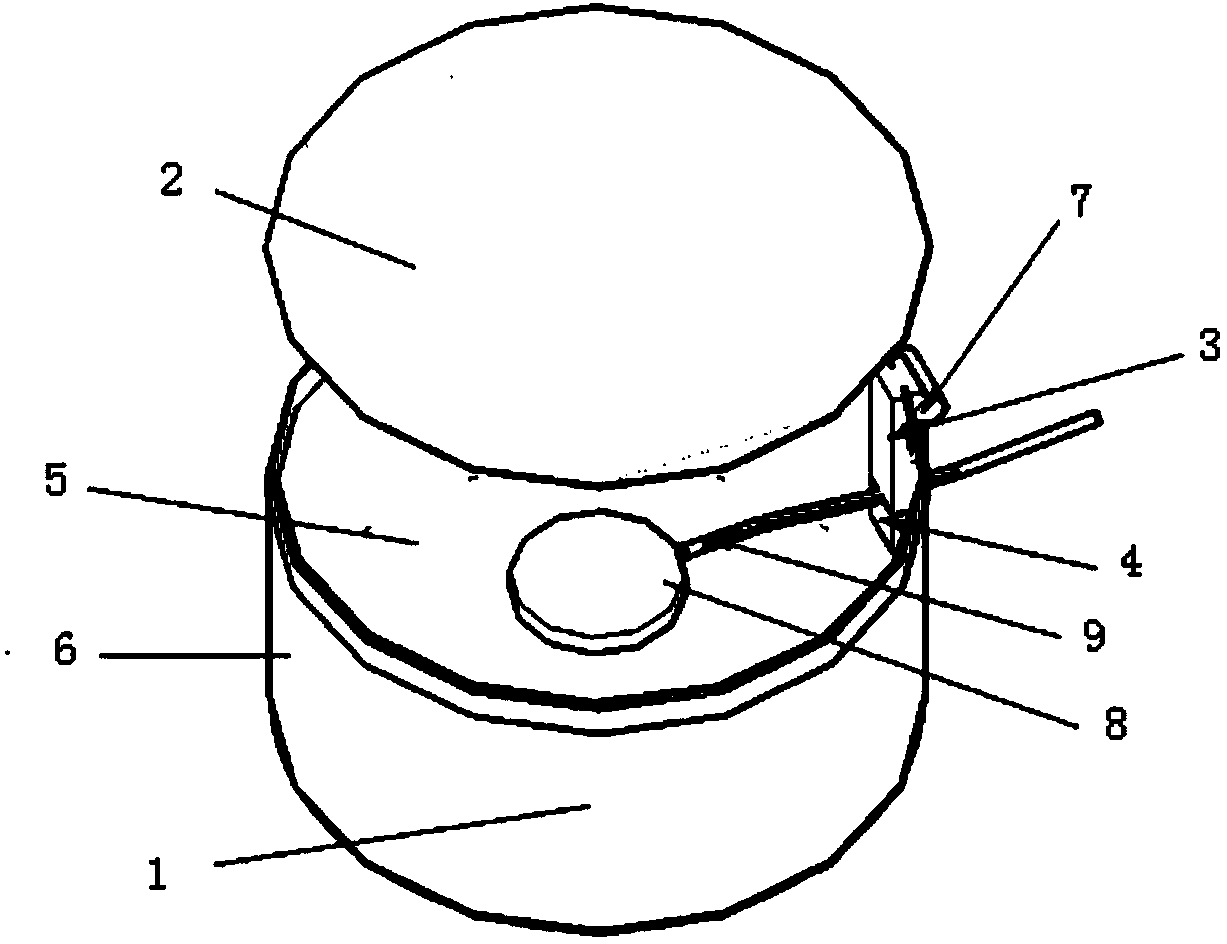
[0051] A device for embedding a rock-earth pressure sensor, comprising a cylindrical thin-walled container 1, a top seat 2, an upper sealing strip 3, a lower sealing strip 4, an inner lining 5, an outer lining 6, a belt 7 and a pressure sensor 8, and the top seat 2 Located on the top of the cylindrical thin-walled container 1, the inside of the cylindrical thin-walled container 1 is provided with a protective layer material, the inner liner 5 is arranged between the cylindrical thin-walled container 1 and the protective layer material, and the outer lining 6 is arranged on the cylindrical thin-walled container 1 outside; the cylindrical thin-walled container 1 is composed of a bottom plate and a side wall, the side wall is provided with a notch, the pressure sensor 8 is located between the protective layer materials, the pressure sensor 8 is connected with the sensor cable 9, and the sensor line The cable 9 extends to the outside through the inner liner 5, the notch on the side...


PUM

PropertyMeasurementUnit
particle diameteraaaaaaaaaa
diameteraaaaaaaaaa
diameteraaaaaaaaaa

Abstract

The invention discloses a rock-soil pressure sensor embedding device and an embedding method thereof. The rock-soil pressure sensor embedding device comprises a cylindrical thin-wall vessel, a base, an upper sealing strip, a lower sealing strip, a lining, an outer lining, a band and a pressure sensor. The embedding method includes: arranging the soil pressure sensor embedding device, digging an embedding hole, levelling the basal plane of the sensor, inverting the pressure sensor embedding device, backfilling the original soil material, extracting the cylindrical thin-wall vessel, and backfilling and so on. By means of the rock-soil pressure sensor embedding device and the embedding method thereof, the digged pit slot is small, the size of a protecting layer needed for the sensor is small, the embedding efficiency is improved, the measuring precision is improved, the protecting layer is avoided from loosening in vibration rolling, and the problem of embedding the sensor in coarse granular materials is solved.

Description

technical field [0001] The invention belongs to the field of geotechnical engineering, in particular to a device for embedding a rock-earth pressure sensor and an embedding method thereof. Background technique [0002] In the current geotechnical engineering, water conservancy and hydropower engineering, and water transportation engineering construction, more and more geotechnical pressure sensors are used to measure the pressure in the medium of coarse-grained materials. Monitor the earth pressure of key parts of the dam body; in road engineering, it is necessary to monitor the subgrade reaction force, and in water transportation engineering, it is often necessary to bury earth pressure gauges to monitor the structural safety; in addition, in scientific research on coarse-grained materials, it is often necessary to The in-situ rock-soil stress data cannot be obtained by conventional indoor experiment methods due to its large particles, and can only be obtained by embedding ...

Claims


Application Information

Patent Timeline
Patent Type & Authority Applications(China)
IPC IPC(8): G01L1/00E02D33/00E02D1/08
Inventor 徐晨李金凤杨安玉邵琪
Owner JSTI GRP CO LTD
Why Eureka
Try Eureka