Condensate water automatic discharging device for preventing air leakage of positive pressure area of air processing device

An air treatment and automatic discharge technology, applied in the direction of preventing condensed water, etc., can solve problems such as air leakage, condensed water backflow, energy waste, etc., and achieve the effect of reliable sealing and preventing air from leaking outward

Inactive Publication Date: 2013-08-14
UNIV OF SHANGHAI FOR SCI & TECH
View PDF6 Cites 5 Cited by
  • Summary
  • Abstract
  • Description
  • Claims
  • Application Information

AI Technical Summary

Problems solved by technology

[0003] The purpose of this invention is to solve two technical problems in the discharge of condensed water in the positive pressure area of ​​the air treatment equipment: (1) When the air treatment equipment uses a U-shaped water seal to isolate the internal and external air, it will cause condensation after shutdown (2) When the air treatment equipment does not take measures to isolate the internal and external air, a large amount of treated air will leak to the outside during operation, resulting in energy waste, and provide an automatic condensate discharge device that prevents air leakage in the positive pressure area of ​​the air handling equipment. Leaking to the outside, the working condition is not affected by the positive pressure in the air handling equipment, and there is no condensed water backflow phenomenon after shutdown

Method used


Image

  • Condensate water automatic discharging device for preventing air leakage of positive pressure area of air processing device
  • Condensate water automatic discharging device for preventing air leakage of positive pressure area of air processing device

Examples


Embodiment Construction

[0010] The present invention will be further described below with reference to the drawings and embodiments.

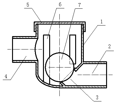
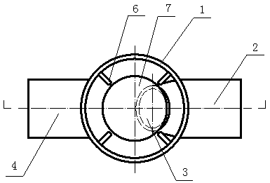
[0011] Such as figure 1 , 2 As shown, the automatic condensate discharge device for preventing air leakage in the positive pressure zone of air treatment equipment of the present invention includes a housing 1, a condensate outlet pipe 2, a drain port 3, a condensate inlet pipe 4, an upper cover 5, and a rib 6, Seal the ball 7.

[0012] The condensate water inlet pipe 4 is connected to the housing 1 at a position close to the upper part, and the condensate water outlet pipe 2 is connected to the housing 1 at a position close to the bottom. The condensate water outlet pipe 2 extends into the housing 1 with an opening on its inner end surface. The lateral drainage port 3 is provided with a sealing ball 7 above the drainage port 3 side, and the sealing ball 7 is connected to the drainage port 3 in a sealed fit.

[0013] The inner wall of the housing 1 has a plurality of ribs 6...


PUM


Abstract

The invention relates to a condensate water automatic discharging device for preventing the air leakage of a positive pressure area of an air processing device. The upper portion of a housing is connected with a condensate water inlet pipe, the lower portion of the housing is connected with a condensate water outlet pipe, the condensate water outlet pipe extends inside the housing, the inside end surface of the condensate water outlet pipe is provided with a lateral draining port, and a sealing ball is arranged above the draining port side of the condensate water outlet pipe and is connected with the draining port in a matching mode. The inner wall of the housing is provided with a plurality of ribs which protrude inwards, the sealing ball is disposed among the rib ends of the housing, and the sealing ball is separated from the rid ends by gaps. The condensate water automatic discharging device can divert condensate water in the positive pressure area of the air processing device outside for discharging, so that the condensate water automatic discharging device for preventing the air leakage of the positive pressure area of the air processing device has the advantage that when the condensate water in the positive pressure area of the air processing device outside is diverted outside for discharging, air inside the air processing device can be prevented from leaking outside through the condensate pipes and the working condition cannot be affected by the positive pressure inside the air processing device, and when the air processing device is powered off, the condensate water cannot backflow. The condensate water automatic discharging device for preventing the air leakage of the positive pressure area of the air processing device is applicable to the discharging of liquid water in the positive pressure areas of various air processing devices or similar devices.

Description

Technical field [0001] The invention relates to a condensate water discharge device used for air conditioning equipment, and in particular to an automatic condensate water discharge device that can prevent air leakage in a positive pressure zone of air processing equipment. Background technique [0002] In the process of cooling and dehumidifying the air in the air treatment equipment of the air conditioning system, part of the water vapor contained in the air will be condensed into liquid water, which is collected in the water collection pan of the air treatment equipment and passes through the condensate drain pipe Discharge to the outside of the air handling equipment. Due to the role of the fan, a negative pressure zone and a positive pressure zone relative to the outside of the air handling equipment are formed before and after the fan of the air handling equipment. When the condensate water collection pan and the condensate drain pipe are located in the negative pressure a...

Claims


Application Information

Patent Timeline
Patent Type & Authority Applications(China)
IPC IPC(8): F24F13/22
Inventor 周志钢盛健赵爱华
Owner UNIV OF SHANGHAI FOR SCI & TECH
Why Eureka
Try Eureka