Device for measuring center distance and gear backlash of gear pair

A technology of backlash and gear pair, which is applied in the measurement field of gear pair, can solve the problems of low measurement accuracy and low efficiency, and achieve the effect of improving measurement accuracy and speed.

Inactive Publication Date: 2015-07-08
XIAMEN GUIGUI NETWORK TECH CO LTD
View PDF7 Cites 0 Cited by
  • Summary
  • Abstract
  • Description
  • Claims
  • Application Information

AI Technical Summary

Problems solved by technology

It is a purely manual measurement method with low efficiency and low measurement accuracy and low efficiency

Method used


Image

  • Device for measuring center distance and gear backlash of gear pair
  • Device for measuring center distance and gear backlash of gear pair
  • Device for measuring center distance and gear backlash of gear pair

Examples


Embodiment 1

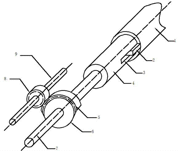
[0025] see figure 1 with figure 2 , the embodiment provides a device for measuring the center distance and backlash of the worm gear pair, including sensor measuring equipment, data processing and display equipment, installation equipment for the driven worm gear pair to be tested, and transmission equipment.

[0026] The installation equipment of the driven worm gear pair to be tested comprises base frame 10 and 11, support frame 12, sliding pallet 13 and 14, sliding support 15; Shaped mandrel 17 rotates together, and brake equipment is installed on the conical mandrel 17, and conical mandrel 17 is installed on the sliding supporting plate 13, and sliding supporting plate 13 can slide on base frame 10, is used for installing, adjusting The driven gear 18 to be measured; the sliding supporting plate 14 can slide up and down along the vertical direction on the support frame 12 to adjust the height of the driving gear 19 to be measured; the left and right sliding brackets 15 a...

Embodiment 2

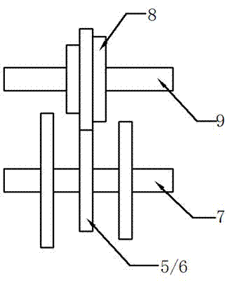
[0035] see Figure 4 with Figure 5 , This embodiment provides a device for measuring the center distance and backlash of spur gear pairs, helical gear pairs, and bevel gear pairs, including sensor measurement equipment, data processing and display equipment, gear pair installation equipment and transmission equipment.

[0036] Described gear pair installation equipment to be tested comprises base frame 10 and 11, support frame 12, sliding pallet 13; Braking equipment is installed on the tapered mandrel 17, and the tapered mandrel 17 is installed on the sliding pallet 13, and the sliding pallet 13 can slide on the base frame 10, and is used for installing and adjusting the driven gear 18 to be tested; The driving gear 19 to be tested is installed on the conical mandrel 16, which can rotate together with the conical mandrel 16. The conical mandrel 16 is installed on the bracket 12; the single-tooth incomplete gear 22 is fixed on the shaft 21, and the shaft 21 Link to each oth...

Embodiment 3

[0041] When the angle α between the driving shaft 1 and the driven shaft 9 in the transmission equipment satisfies 0<α<90°, some special meshing gears can be measured by refitting the gear pair installation equipment to be tested. The measurement principle is the same as The foregoing embodiments are the same, and will not be described in detail here.


PUM


Abstract

The invention discloses a device for measuring the center distance and the gear backlash of a gear pair. The device comprises to-be-measured gear pair installation equipment and transmission equipment. The to-be-measured gear pair installation equipment comprises base frames, a support frame and braking equipment of a to-be-measured driven gear, wherein the support frame is arranged on the base frames and is capable of horizontally moving on the base frames. The transmission equipment comprises a cam shaft, a driving shaft and a driven shaft. The transmission equipment is arranged in the support frame; the cam shaft and the driving shaft are the same shaft or two shafts which are in rigid connection; the end part of the cam shaft is provided with a cam; the cam is contacted with the fixed base frames; the driving shaft is provided with an imperfect gear; the driven gear is arranged on the driven shaft; and a to-be-measured driving gear is driven by the driven shaft to rotate. The device is automatic measuring equipment and has functions of automatic measurement, automatic reading and automatic graph and data generation. Not only is the measurement accuracy improved but also the measuring speed is greatly increased. Moreover, the measurement of the gear pair with various transmission ratios can be realized.

Description

technical field [0001] The invention belongs to the measurement field of gear pairs, in particular to a device for measuring the center distance and tooth side clearance of gear pairs. Background technique [0002] In order to ensure the normal meshing operation of the gear pair, oil film lubrication is required between the working tooth surfaces, and the influence of factors such as temperature rise and deformation must be considered between the non-working tooth surfaces. Therefore, between the working tooth surfaces and the non-working tooth surfaces of the gear pair There should be sufficient but not too large side clearance for oil storage and compensation for thermal expansion; in addition, it is also necessary to ensure that the center distance of the gear pair meets the design requirements. [0003] There are single-point method, single-mesh method and double-mesh method for measuring the backlash of gear pairs. The single-point method is used to measure the install...

Claims


Application Information

Patent Timeline
Patent Type & Authority Patents(China)
IPC IPC(8): G01B21/16
Inventor 雷定中程东霁张刚蒋文斌胡雯婷
Owner XIAMEN GUIGUI NETWORK TECH CO LTD
Why Eureka
Try Eureka