Eureka AIR delivers breakthrough ideas for toughest innovation challenges, trusted by R&D personnel around the world.

Knock detection device of internal combustion engine

A technology for detection devices and internal combustion engines, which is applied to measuring devices, internal combustion piston engines, combustion engines, etc., can solve the problems of small knock judgment value and misjudgment, and achieve the effect of ensuring tracking

Active Publication Date: 2013-08-14
MITSUBISHI ELECTRIC CORP +1
View PDF5 Cites 3 Cited by
  • Summary
  • Abstract
  • Description
  • Claims
  • Application Information

AI Technical Summary

Problems solved by technology

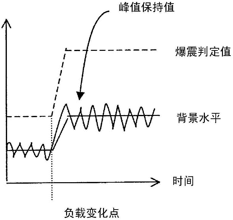
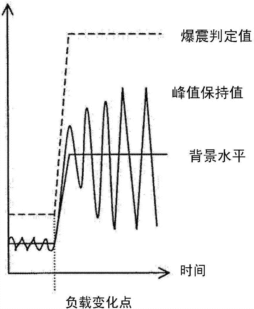
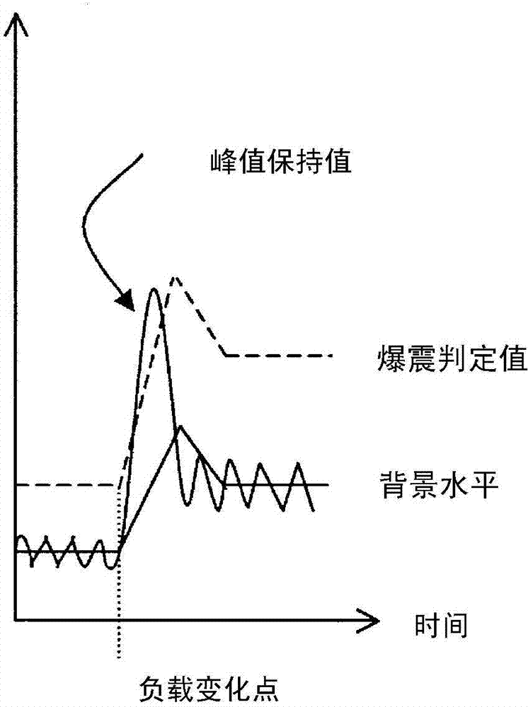
Its purpose is to cope with the following phenomenon, that is, when the load on the engine increases, the peak hold value increases even when knocking does not occur, but if the stabilization is continued through smoothing processing or update amount limiting processing, Then the background level will not rise immediately, and as a result, the knocking judgment value is too small, which will lead to false judgment of knocking

Method used


Image

  • Knock detection device of internal combustion engine
  • Knock detection device of internal combustion engine
  • Knock detection device of internal combustion engine

Examples


Embodiment approach 1

[0073] Hereinafter, a knock control device using the knock detection device for an internal combustion engine according to Embodiment 1 of the present invention will be described in detail with reference to the drawings. Image 6 It is a configuration diagram schematically showing an internal combustion engine including a knock control device using the knock detection device according to Embodiment 1 of the present invention. In addition, an internal combustion engine for a vehicle such as an automobile generally includes a plurality of cylinders and pistons, but Image 6 For the sake of illustration, only one cylinder and piston are shown.

[0074] exist Image 6 In the air intake system 100 of the internal combustion engine 1, an air flow sensor 2 for measuring the intake air flow rate and outputting an intake air flow signal corresponding to the measured value is provided from the upstream side, and the opening degree is electronically controlled to adjust further. The el...

Embodiment approach 2

[0120] A knock detection device for an internal combustion engine according to Embodiment 2 will be described. Embodiment 2 differs from Embodiment 1 in the calculation method of the maximum value L of the peak hold value, so this part will be described. The maximum value L of the peak hold value is defined depending on the rotational speed ne of the internal combustion engine. The setting method of L is the same as that of Embodiment 1. The data of the peak hold value under various operating states and loads of the internal combustion engine without knocking are obtained, and the maximum value is classified by the speed ne of the internal combustion engine, and is set as tabular data. This is Figure 5 The case of L, for example, such as Figure 10 Set it that way.

[0121] exist Figure 8 In the maximum value L of the peak hold value labeled 22, use the speed ne to Figure 10The interpolation is performed in the table, and the result is used as the maximum value L of t...


PUM


Abstract

In order to obtain a knock detection device of an internal combustion engine which satisfies two objects of following capability and separation from a continuous knock generation state, when a background level is calculated by ((current background level)=(filter coefficient)×(previous background level)+(1-filter coefficient)×(output signal from knock sensor)), updating quantity of the background level is limited by ((1-filter coefficient)×(value not lower than maximum value of output signal from knock sensor at time when knock is not generated)).

Description

technical field [0001] The present invention relates to background level calculation in a knock detection device for an internal combustion engine that calculates a background level based on a detected output signal from a knock sensor and derives a knock determination value from the background level for knock determination. Background technique [0002] In a gasoline-fueled engine, etc., during the combustion stroke, the mixture in the cylinder is ignited and combusted by the spark from the spark plug, but when the pressure in the cylinder increases abnormally during the flame propagation after ignition, the flame Detonation with spontaneous combustion of the unburned portion of the mixture sometimes occurs before propagation is complete. In addition, when the knocking occurs, vibrations that give a strange feeling to the occupants are generated, and in severe cases, the upper surface of the piston is melted and damaged, causing problems such as engine failure. Therefore, ...

Claims


Application Information

Patent Timeline
Patent Type & Authority Applications(China)
IPC IPC(8): F02D43/00G01H17/00G01L23/22
CPCF02D41/22F02D43/00F02D2041/1432F02D41/1401F02D35/027G01H17/00F02P5/152G01L23/22Y02T10/46G01L23/225Y02T10/40
Inventor 田仲彻松嶋裕平江角圭太郎楠友邦井上淳森本博贵
Owner MITSUBISHI ELECTRIC CORP
Why Eureka
Eureka Blog
Learn More