Photosensitive drum drive gear and toner cartridge

A photosensitive drum drive and photosensitive drum technology, applied in optics, electrical recording, instruments, etc., can solve problems such as increased difficulty, instability, and unstable rotation, and achieve reduced maintenance costs, easy assembly and operation, and uniform transmission force Effect

Active Publication Date: 2015-11-18
ZHUHAI SOMEWAY ELECTRONICS SCI & TECH
View PDF8 Cites 0 Cited by
  • Summary
  • Abstract
  • Description
  • Claims
  • Application Information

AI Technical Summary

Problems solved by technology

However, due to the existence of precision errors in each of the existing processing technologies, the driving head of each driving gear and the driving port of each driving part in each batch of the same production line are different, and eventually the driving head cannot be snapped in. The drive port cannot be used, or the drive head cannot be smoothly inserted into the drive port and repeated operations, or the connection is loose and unsatisfactory, resulting in uneven and uneven transmission force; and once the drive head is damaged, the entire drive gear can only be disassembled and discarded. Replacing another driving gear not only increases the maintenance cost, but also causes pollution to the environment; and the existing driving head is usually designed as a twisted triangle, which makes the mold structure of the entire driving gear very complicated, greatly improving mold processing and product production. In addition, because the ends of these triangular drive heads are all pointed, they are in point contact with the drive port of the printer drive unit, the drive gears are not uniformly stressed, and the rotation is unstable, resulting in problems such as gear lines in toner cartridge products.

Method used


Image

  • Photosensitive drum drive gear and toner cartridge
  • Photosensitive drum drive gear and toner cartridge
  • Photosensitive drum drive gear and toner cartridge

Examples


Embodiment Construction

[0022] In order to make the object, technical solution and advantages of the present invention clearer, the present invention will be further described in detail below in conjunction with the accompanying drawings and embodiments. It should be understood that the specific embodiments described herein are intended to illustrate the present invention.

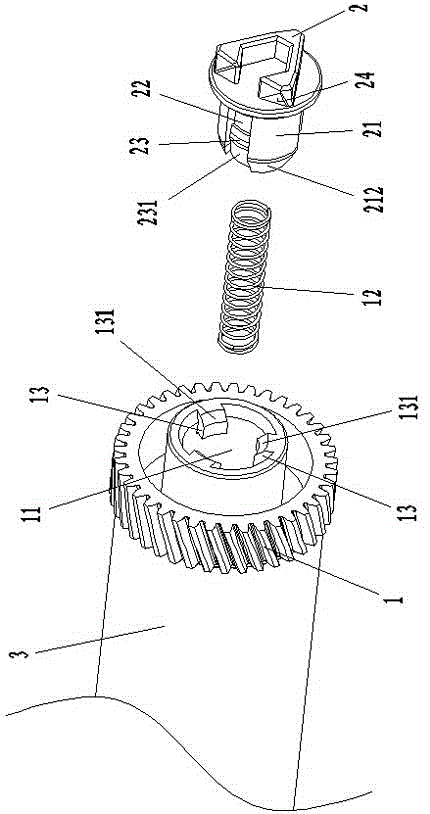
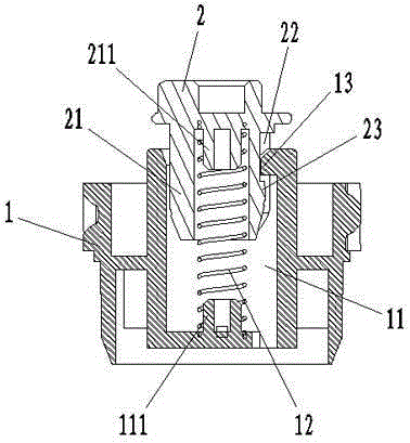
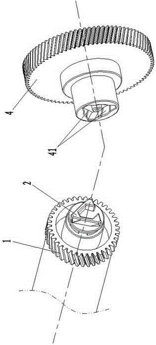
[0023] like Figure 1 to Figure 4 as shown in:

[0024] A photosensitive drum driving gear described in the embodiment of the present invention includes a gear main body 1 with one end mounted on the photosensitive drum 3, and the other end of the gear main body 1 is provided with a driving head 2 connected with the printer. 2 is flexibly connected with the gear main body 1 in such a way that it can be compressed back and spring up automatically, and the gear main body 1 and the driving head 2 are in a split structure, and the driving head 2 is detachably and replaceably set at the other end of the gear main body 1 . The specif...


PUM


Abstract

The invention relates to a driving gear for a photosensitive drum and a carbon powder box. The driving gear comprises a gear main body, wherein one end of the gear main body is arranged on the photosensitive drum, and the other end of the gear main body is provided with a driving head which is connected with a printer; the driving head is designed to be of a V shape, and the outer side surface of the driving head is an inclined untwisted plane; and the driving head is arranged at the other end of the gear main body in a retracting during downwards pressing, automatic springing and detachable replacing manner. Therefore, the driving head is clamped into a driving port smoothly and is fully engaged when the carbon powder box is installed in the printer, so that transmission stress is uniform and steady; and when being damaged, the driving head is replaced, the whole driving gear does not need to be abandoned, the maintenance cost is reduced, the waste is reduced, and the aim of environmental protection can be fulfilled. Compared with a conventional twisted triangular driving head, for the driving gear for a photosensitive drum, the V-shaped driving head of which the outer side surface is the inclined untwisted plane is reasonable in mold structure.

Description

technical field [0001] The invention belongs to the technical field of photosensitive drums and toner boxes, and relates to a photosensitive drum driving gear and a toner box using the photosensitive drum driving gear. Background technique [0002] At present, the photosensitive drum in all toner cartridges on the market is equipped with a driving gear at one end, and the driving gear is provided with an integrally formed driving head, which is connected with the driving part in the printer to drive the photosensitive drum. The drum spins. However, due to the existence of precision errors in each of the existing processing technologies, the driving head of each driving gear and the driving port of each driving part in each batch of the same production line are different, and eventually the driving head cannot be snapped in. The drive port cannot be used, or the drive head cannot be smoothly inserted into the drive port and repeated operations, or the connection is loose and...

Claims


Application Information

Patent Timeline
Patent Type & Authority Patents(China)
IPC IPC(8): G03G15/00G03G15/08
Inventor 冉启国
Owner ZHUHAI SOMEWAY ELECTRONICS SCI & TECH
Why Eureka
Try Eureka