System control apparatus and system control method

A control device and manufacturing system technology, which is applied to program control, temperature control, adaptive control, etc. in sequence/logic controllers, and can solve the problems that it is difficult to consider the impact of sudden interference, it is too late to control the drive device, and the state data exceeds the benchmark Questions like value or base range

Inactive Publication Date: 2013-08-14
ORMON CORP
View PDF6 Cites 10 Cited by
  • Summary
  • Abstract
  • Description
  • Claims
  • Application Information

AI Technical Summary

Problems solved by technology

[0016] However, in the technologies described in Patent Document 1 and Patent Document 2, control is performed by comparing the detection value of the sensor with a fixed control value, and when there is a margin between the detection value of the sensor and the above-mentioned control value, In this case, it is considered that the driving device is excessively controlled and energy is wasted
In addition, in such a technology, when the disturbance has a great influence on the system, it is too late to control the driving device, which may cause the above-mentioned state data to exceed the reference value or the reference range.
In addition, in such a technique, since the setting is made based on the experience and feeling of the system administrator, etc., there is also a problem that it is impossible to grasp in advance the degree of security of the control using the status data as described above. and the extent to which energy savings can be achieved
[0017] In the technology described in Patent Document 3, when it is judged that there is regularity, control is performed according to the regularity, but at this time it is difficult to consider the influence of sudden disturbance
In addition, in the techniques described in Patent Document 4 and Patent Document 5, future state data is predicted based on past state data, but it is also difficult to consider the influence of disturbance in this prediction.
Therefore, it is still difficult to reliably converge the state data of the system to the reference value or reference range

Method used


Image

  • System control apparatus and system control method
  • System control apparatus and system control method
  • System control apparatus and system control method

Examples


no. 1 approach ]

[0063]

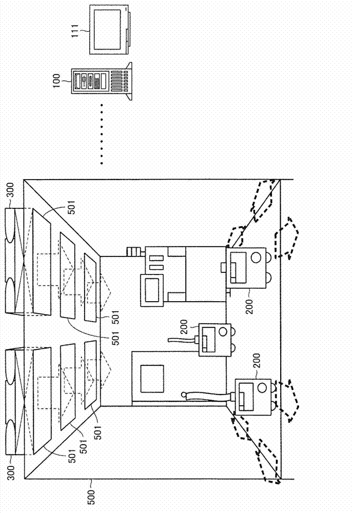
[0064] figure 1 It is a figure which schematically shows the outline structure of the manufacturing system including the system control apparatus which is 1st Embodiment of this invention.

[0065] refer to figure 1 , the manufacturing system includes a clean booth 500 as a space for manufacturing products. A particle sensor 200 for detecting the degree of cleanliness in the clean room 500 is provided in the clean room 500 . Although in figure 1 Although illustration is omitted in FIG. 1 , a production line for manufacturing products is installed in the clean room 500 , and workers who manage the production line and the like are arranged.

[0066] Frames 501 are formed on the ceiling of the clean room 500, and filter fan units (FFU) 300 are provided on each frame 501. 500 fans outside the room.

[0067] exist figure 1 In , the dotted arrows indicate the flow of air. In the clean room 500, by the operation of the fan of the filter fan unit 300 (hereinafter, so...

no. 2 approach ]

[0135]

[0136] In the present embodiment, in the control of the equipment (filter fan unit 300 ) realized by the controller 100 , a plurality of estimated values ​​are derived stepwise. Figure 13 It is a figure for demonstrating the outline|summary of the control of this embodiment.

[0137] exist Figure 13 The setting conditions of the air volume of the fan of the filter fan unit 300 and the controlled air volume of the fan are shown in . In addition, in Figure 13 Herein, regarding the reference value, the case where only the reference value on the upper side is set will be described as in the first embodiment.

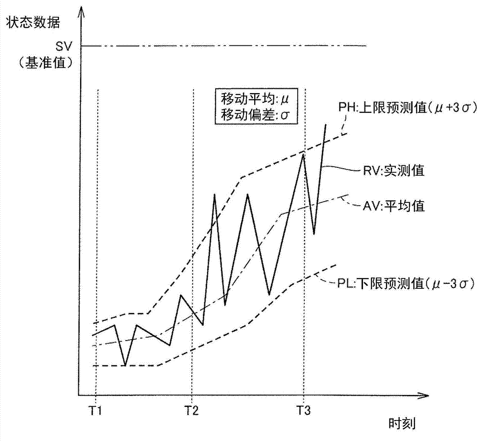
[0138] In the present embodiment, a plurality of predicted values ​​calculated using the moving average μ and moving deviation σ obtained as described above are compared with the reference value, and the air volume of the filter fan unit 300 is determined based on the comparison result.

[0139] Specifically, a plurality of predicted values ​​("μ+6σ", "μ+5σ"...

Embodiment )

[0162] Figure 20 It is a graph showing a specific example of the temporal change of the actually measured value of the state data, the first to fourth upper limit predicted values, and the air volume level of the filter fan unit 300 . exist Figure 20 In , the temporal change of the air volume level is shown in the upper row, and the actual measurement value and predicted value of the state data are shown in the lower row.

[0163] In addition, the graph in the lower stage shows the amount of foreign matter contained per unit volume detected by the particle sensor 200 as a specific example of state data. Then, with respect to the amount of foreign matter, the actual measured value is shown by the line R, the first upper limit predicted value is shown by the line D1, the second upper limit predicted value is shown by the line D2, and the third upper limit predicted value is shown by the line D3. The fourth upper limit predicted value is represented by line D4. in addition, ...


PUM


Abstract

A system control apparatus and a system control method in which, when a state of a production system is maintained at a reference value or within a reference range, a state of the production system is surely controlled while generation of useless energy is avoided and a user can recognize a degree of energy saving. In consideration of an influence of a disturbance, a prediction range is derived with respect to data ("status data") indicating the state in which quality of a product produced by the production system, and an instrument is controlled based on a relationship between the prediction range and the reference value. Therefore, the instrument can be controlled in consideration of a variation in status data due to the influence of the disturbance.

Description

technical field [0001] The present invention relates to the control of the system, in particular to a system control device and a system control method for controlling equipment used to adjust the characteristics of the system based on the detection results of the system characteristics. Background technique [0002] Conventionally, some systems for producing products, etc., have been provided with devices that indicate the status of data that will affect the quality of products manufactured by the system (hereinafter referred to as "status data") , equipment that remains within a predetermined reference value or reference range. In addition, as the above-mentioned data, for example, the temperature and humidity of the room where the system is installed, the differential pressure between the room where the system is installed and the outside, the noise level of the room to be controlled by the system, The size, roundness, sphericity and parallelism of the products (or semi-...

Claims


Application Information

Patent Timeline
Patent Type & Authority Applications(China)
IPC IPC(8): G05B19/04G05D23/20F24F11/00
CPCG05B19/02G05B13/026F24F11/0017F24F2011/0093F24F3/161Y02B30/78F24F11/30F24F2110/50F24F11/39Y02P80/10Y02P90/80Y02B30/70F24F11/77F24F11/46F24F11/64
Inventor 八竹英纪服部玲子
Owner ORMON CORP
Why Eureka
Try Eureka