Remote fluorescent powder and preparation method thereof

A technology of remote phosphors and phosphors, applied in electrical components, circuits, semiconductor devices, etc., can solve the problems of destroying the crystal structure of phosphors, low LED lighting brightness, surface defects of crystal particles, etc., achieving high lighting brightness and simple materials. , the effect of small light decay

Inactive Publication Date: 2013-08-14
RAYPOWER OPTOELECTRONICS SUZHOU
View PDF4 Cites 2 Cited by
  • Summary
  • Abstract
  • Description
  • Claims
  • Application Information

AI Technical Summary

Problems solved by technology

The disadvantages are: the external mechanical shear force during extrusion is easy to destroy the crystal structure of the phosphor, causing defects on the surface of the crystal particles, resulting in low brightness of LED lighting and large light attenuation

Method used


Image

  • Remote fluorescent powder and preparation method thereof

Examples


Embodiment Construction

[0019] The following descriptions are only preferred embodiments of the present invention, and therefore do not limit the protection scope of the present invention.

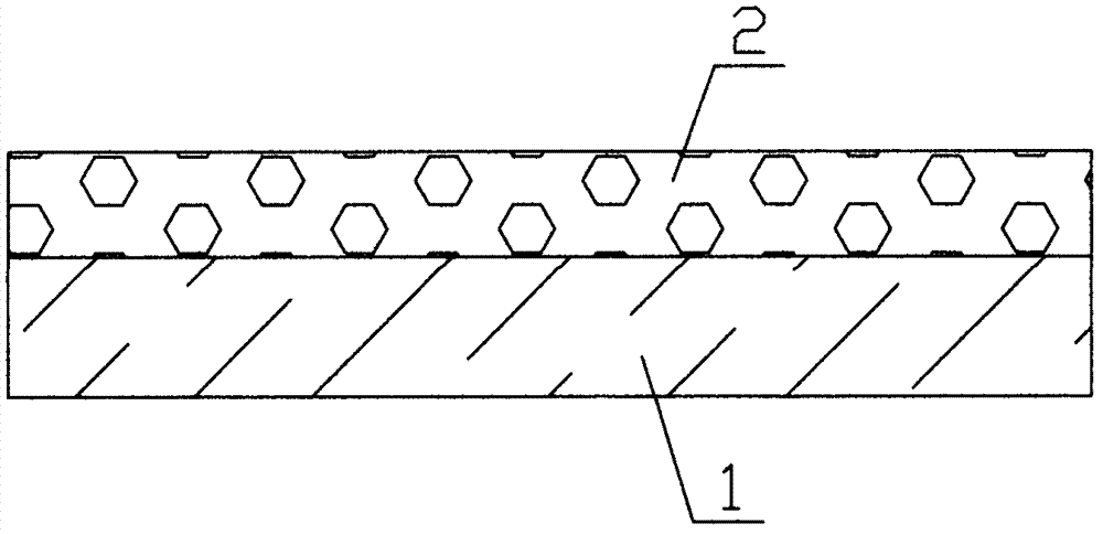
[0020] Examples, see figure 1 Shown: remote phosphor, including transparent resin layer 1 and phosphor layer 2. Wherein, the phosphor layer 2 is disposed on one side surface of the transparent resin layer 1 . The phosphor layer 2 can adopt various common phosphor layers. Optimally, the phosphor layer 2 is a mixture of phosphor, binder and coupling agent. Of course, the adhesive can be a common water-resistant or water-soluble adhesive, and the coupling agent can be a common material such as a silane coupling agent. Further, the weight ratio of the phosphor powder, binder and coupling agent in the phosphor powder layer 2 is 100:(0.01-1):(0.01-1). Optimally, the weight ratio of phosphor powder, binder and coupling agent in the phosphor powder layer 2 is 100:0.05:0.05.

[0021] The preparation method adopted fo...


PUM


Abstract

The invention discloses remote fluorescent powder which comprises a transparent resin layer and a fluorescent powder layer, wherein the fluorescent powder layer is arranged on the surface of one side of the transparent resin layer. After optimized, the fluorescent powder layer is a mixture of fluorescent powder, adhesive and a coupling agent. The powder has the advantages of high illumination brightness and low light decay. The invention further discloses a preparation method of the remote fluorescent powder.

Description

technical field [0001] The invention relates to the technical field of LED lighting devices, in particular to a remote fluorescent powder and a preparation method thereof. Background technique [0002] Traditional LED lighting uses yellow phosphor and silica gel to mix and adjust the glue, and then dispense the mixed glue on the chip. Although this method is simple to operate, the heat dissipation of the chip after packaging is poor, resulting in a large light decay of the phosphor, and uneven luminescence is prone to occur. For this reason, people use the method that the phosphor powder and the chip do not directly contact, that is, the remote phosphor method, to effectively improve the light attenuation problem. Typically, remote phosphors are formed by adding LED phosphors to plastic and then extruding them through a screw. Its disadvantages are: the external mechanical shear force during extrusion is easy to destroy the crystal structure of the phosphor, causing defect...

Claims


Application Information

Patent Timeline
Patent Type & Authority Applications(China)
IPC IPC(8): H01L33/50
Inventor 牟文斌付成国
Owner RAYPOWER OPTOELECTRONICS SUZHOU
Why Eureka
Try Eureka