Acoustic generator with elastic position correction function

A generator and functional technology, applied in the field of sound waves, can solve problems such as the inability to generate actual electric energy that can be output and applied, the inability to collect and make full use of sound energy, and the inability to convert sound energy and electric energy. High electrical conversion efficiency and reduced sound energy loss

Inactive Publication Date: 2013-08-14
SHANGHAI DIANJI UNIV
View PDF5 Cites 0 Cited by
  • Summary
  • Abstract
  • Description
  • Claims
  • Application Information

AI Technical Summary

Problems solved by technology

[0002] At present, sound wave power generation is a new type of power generation method, which is still in the development stage, and there are not many sound-to-electricity conversion systems that can be applied to production and life.
However, more acoustic and electrical equipment used for sound collection and sensing only focus on sound quality and real output, and cannot collect and make full use of the energy in sound.
Some known devices that generate electri

Method used


Image

  • Acoustic generator with elastic position correction function
  • Acoustic generator with elastic position correction function
  • Acoustic generator with elastic position correction function

Examples


Embodiment 1

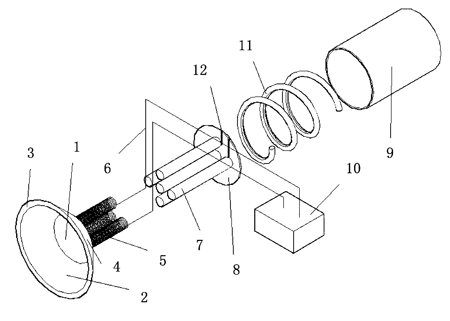
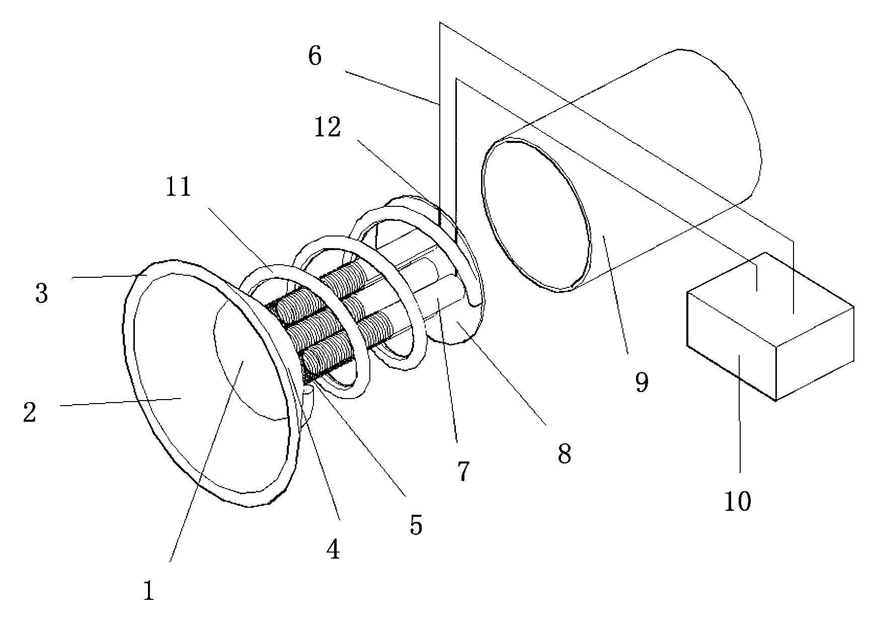
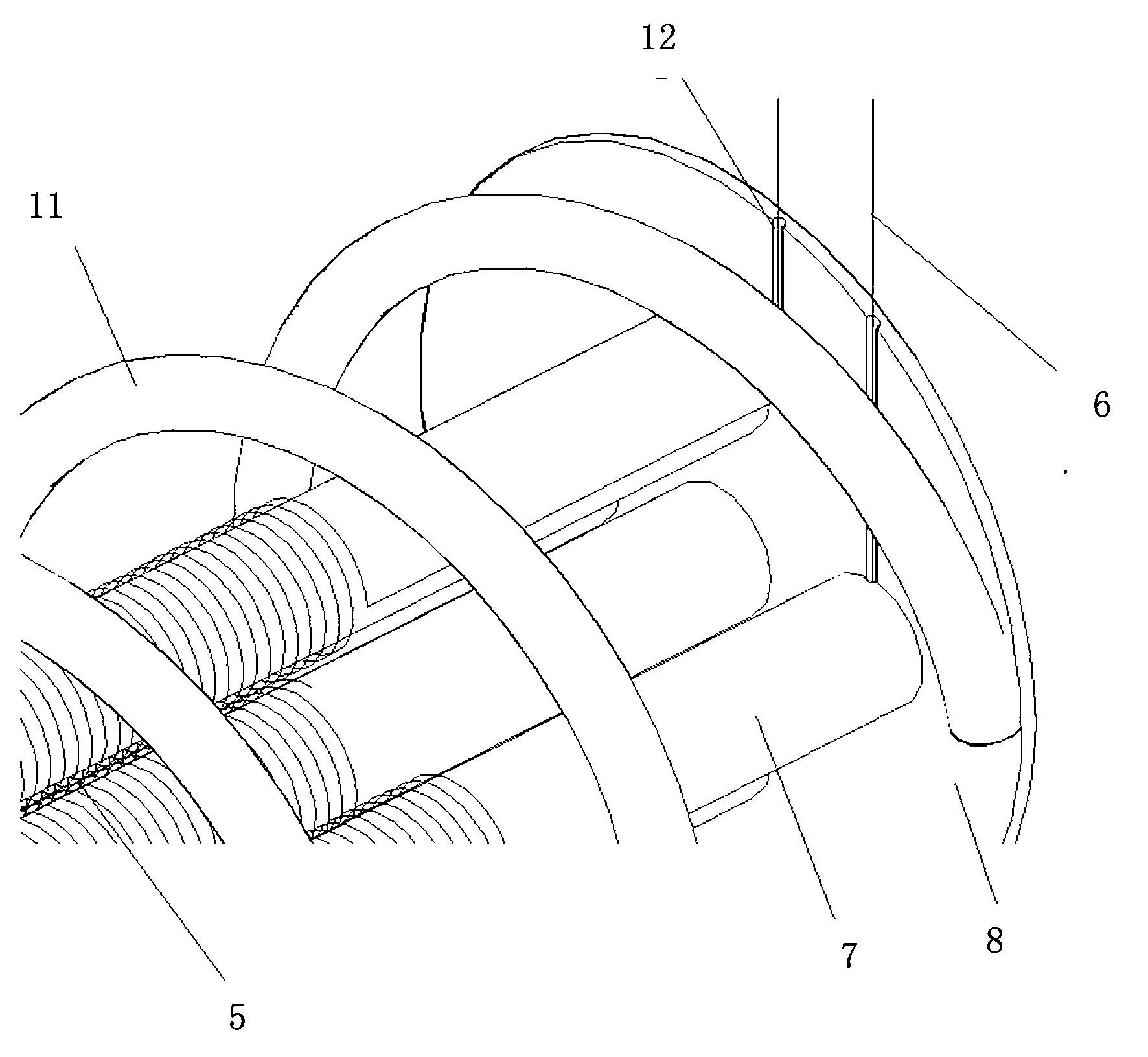
[0044] In areas with relatively high noise, such as an airport, multiple sound wave generators are installed on the metal plate, and the sound wave generators face the sound source. The paper cone 2 of the acoustic wave generator vibrates to a certain extent due to the action of sound energy such as noise, and then drives the synchronous vibration of the generating coil 5, so that the vibration of the generating coil 5 cuts the magnetic field lines of the magnet 7, and generates electrical energy. The generated electric energy is transmitted to the power transmission target device 10 through the power transmission wire 6 . Since a plurality of acoustic wave generators work together, the currents output by the plurality of acoustic wave generators can be fed into the same power transmission target device 10 . Then, the integration of the power transmission target device 10 is output to the power supply device.

Embodiment 2

[0046] The acoustic wave generator is arranged on or inside the shell of complex large-scale mechanical equipment without affecting the work of the mechanical equipment. The acoustic wave generator collects the noise emitted by the mechanical equipment, converts it into an electrical signal and outputs it to the power transmission target equipment 10, and provides computer analysis and processing, that is, compares the collected actual electrical signal with the reference electrical signal preset in the computer. The signals are compared, and the preset reference electrical signal is obtained by collecting and converting the mechanical equipment when it is working normally. Therefore, the characteristics of the actual electrical signal are analyzed by the computer to judge whether the mechanical equipment is working normally.


PUM


Abstract

The invention provides an acoustic generator with an elastic position correction function, which comprises a connecting surface, a paper cone, a cone frame, a connecting body for the paper cone and the cone frame, power generating coils, power transmission conductors, magnetic bodies, a base, a housing and a power transmission target device, wherein one side of the connecting surface is connected with the paper cone, the other side of the connecting surface is connected with the power generating coils, the paper cone is used for receiving the sound energy generated from the external environment to vibrate, and the vibration is sent to the power generating coil through the connecting surface, so as to enable the power generating coils to vibrate; the connecting body for the paper cone and the cone frame is used for enabling the paper cone to move inwards to the original position under the action of the sound energy; the cone frame is connected with the housing; one ends of the power transmission conductors are connected to the two ends of the power generating coils, the other ends of the power transmission conductors penetrate the base and are connected with the target power transmission device; the magnetic body is fixed on the base, and one ends of the magnetic bodies are inserted in the power generating coils; and the base is fixedly connected with the housing.

Description

technical field [0001] The invention relates to the field of sound wave technology, in particular to a sound wave generator with an elastic position correction function. Background technique [0002] At present, sound wave power generation is a new type of power generation method, which is still in the development stage, and there are not many sound-to-electricity conversion systems that can be applied to production and life. However, more acoustic and electrical equipment used for sound collection and sensing only focus on sound quality and real output, and cannot collect and make full use of the energy in sound. Some known devices for generating electricity through sound energy have the following disadvantages: 1) The number is small and most of them have complex structures, or are large in size, which is not convenient for wide application. 2) Most of the existing acoustic-electric conversion technologies cannot effectively convert acoustic energy and electrical energy. ...

Claims


Application Information

Patent Timeline
IPC IPC(8): H02K35/04
Inventor 吉晓乐关宇晨潘景齐笪建怿杜浩明
Owner SHANGHAI DIANJI UNIV
Why Eureka
Try Eureka