High-capacity centrifugal machine rotor and continuous flow centrifugal machine

A centrifuge rotor and large-capacity technology, which is applied in centrifuges and other directions, can solve the problems of low centrifugation efficiency, limited volume, and long centrifugation operation time, so as to improve centrifugation efficiency, shorten centrifugation operation time, and collect precipitated solids. Effect

Inactive Publication Date: 2013-08-21
苏州杰诺曼博生物科技有限公司
View PDF9 Cites 4 Cited by
  • Summary
  • Abstract
  • Description
  • Claims
  • Application Information

AI Technical Summary

Problems solved by technology

If the traditional centrifugation method is used, the mixed solution to be centrifuged is placed in a centrifuge bottle or centrifuge tube, and then placed in the rotor of a refrigerated centrifuge for centrifugation. Due to the limited capacity of the centrifuge bottle or centrifuge tube (the capacity of the centrifuge bottle is generally ...

Method used


Image

  • High-capacity centrifugal machine rotor and continuous flow centrifugal machine

Examples


Embodiment Construction

[0012] The present invention will be described below in conjunction with the accompanying drawings and specific embodiments. The given embodiments are only general illustrations of the present invention, which are helpful for a better understanding of the present invention, but do not limit the scope of the present invention.

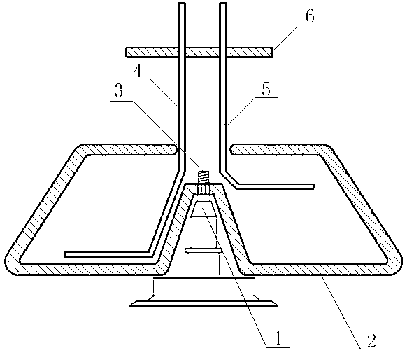
[0013] see figure 1 The large-capacity centrifuge rotor of the present invention includes a rotor 2, the rotor 2 is a hollow trapezoidal cylinder with an inlet and outlet hole in the center of the top, and the center of the bottom of the trapezoidal cylinder has a groove that is sunken inward. There is a shaft hole at the bottom of the groove, and the usual inlet and outlet holes are round holes, and the bottom of the groove is close to the inlet and outlet holes, so that the rotor 2 forms a structure similar to a trapezoidal ring cylinder. Specifically, the The rotor 2 is a central axis symmetrical structure. Through the design of this structure, duri...


PUM


Abstract

The invention discloses a high-capacity centrifugal machine rotor which comprises a rotor body. The rotor body is a hollow trapezoid cylinder body, wherein a material inlet and outlet is formed in the center of the top portion, a groove which sinks inwards is formed in the central position of the bottom portion of the trapezoid cylinder body, and a shaft hole is formed in the bottom portion of the groove. The invention further discloses a continuous flow centrifugal machine which comprises the high-capacity centrifugal rotor. The continuous flow centrifugal machine comprises a centrifugal machine main shaft, a liquid inlet pipe and a liquid outlet pipe, wherein the liquid inlet pipe and the liquid outlet pipe stretch into the inner portion of the rotor body through the material inlet and outlet, and the top end of the centrifugal machine main shaft penetrates through the shaft hole. The rotor body is erected and fixed on the centrifugal machine main shaft through a rotary shaft nut and a gasket corresponding to the rotary shaft nut so that the rotor body can rotate as the centrifugal machine main shaft rotates. Through the high-capacity centrifugal machine rotor and the continuous flow centrifugal machine, a large amount of mixed liquid can be centrifuged continuously, sedimentary solid-state substances can be collected conveniently, separation of liquid-state /solid-state substances in the mixed liquid can be completed at one time, centrifugal separation efficiency is improved greatly and centrifugal operating time is shortened.

Description

technical field [0001] The invention relates to a centrifuge rotor and a continuous flow centrifuge equipped with the centrifuge rotor, in particular to a centrifuge rotor capable of centrifuging a large-capacity mixed liquid and a corresponding continuous flow centrifuge. Background technique [0002] A centrifuge is a special instrument that uses centrifugal force to separate and settle a mixed solution containing solids. Laboratories often use centrifuges for a large number of primary separations to extract biomacromolecules, sediments, etc., especially low-speed refrigerated centrifuges. If the traditional centrifugation method is used, the mixed solution to be centrifuged is placed in a centrifuge bottle or centrifuge tube, and then placed in the rotor of a refrigerated centrifuge for centrifugation. Due to the limited capacity of the centrifuge bottle or centrifuge tube (the capacity of the centrifuge bottle is generally 300ml ~500ml, the capacity of the centrifuge tu...

Claims


Application Information

Patent Timeline
IPC IPC(8): B04B7/00B04B5/12B04B11/02
Inventor 谢伟胜张科之
Owner 苏州杰诺曼博生物科技有限公司
Why Eureka
Try Eureka