Bonding wire cutting machine and bonding wire cutting control method

A control method and cutting machine technology, applied in the field of cutting machines, can solve the problems of personnel burns, welding explosions, etc.

Inactive Publication Date: 2013-08-21
CAL COMP OPTICAL ELECTRONICS SUZHOU +1
View PDF5 Cites 3 Cited by
  • Summary
  • Abstract
  • Description
  • Claims
  • Application Information

AI Technical Summary

Problems solved by technology

[0004] However, since the welding wire contains a rosin layer, it is very easy to produce a welding explosion phenomenon during welding, thereby leaving small welding beads splashed everywhere on the object to be welded (such as a printed circuit board), and even the welding explosion occurs Small welding beads splashed at high speed will cause burns due to its high temperature, which is not ideal

Method used


Image

  • Bonding wire cutting machine and bonding wire cutting control method
  • Bonding wire cutting machine and bonding wire cutting control method
  • Bonding wire cutting machine and bonding wire cutting control method

Examples


Embodiment Construction

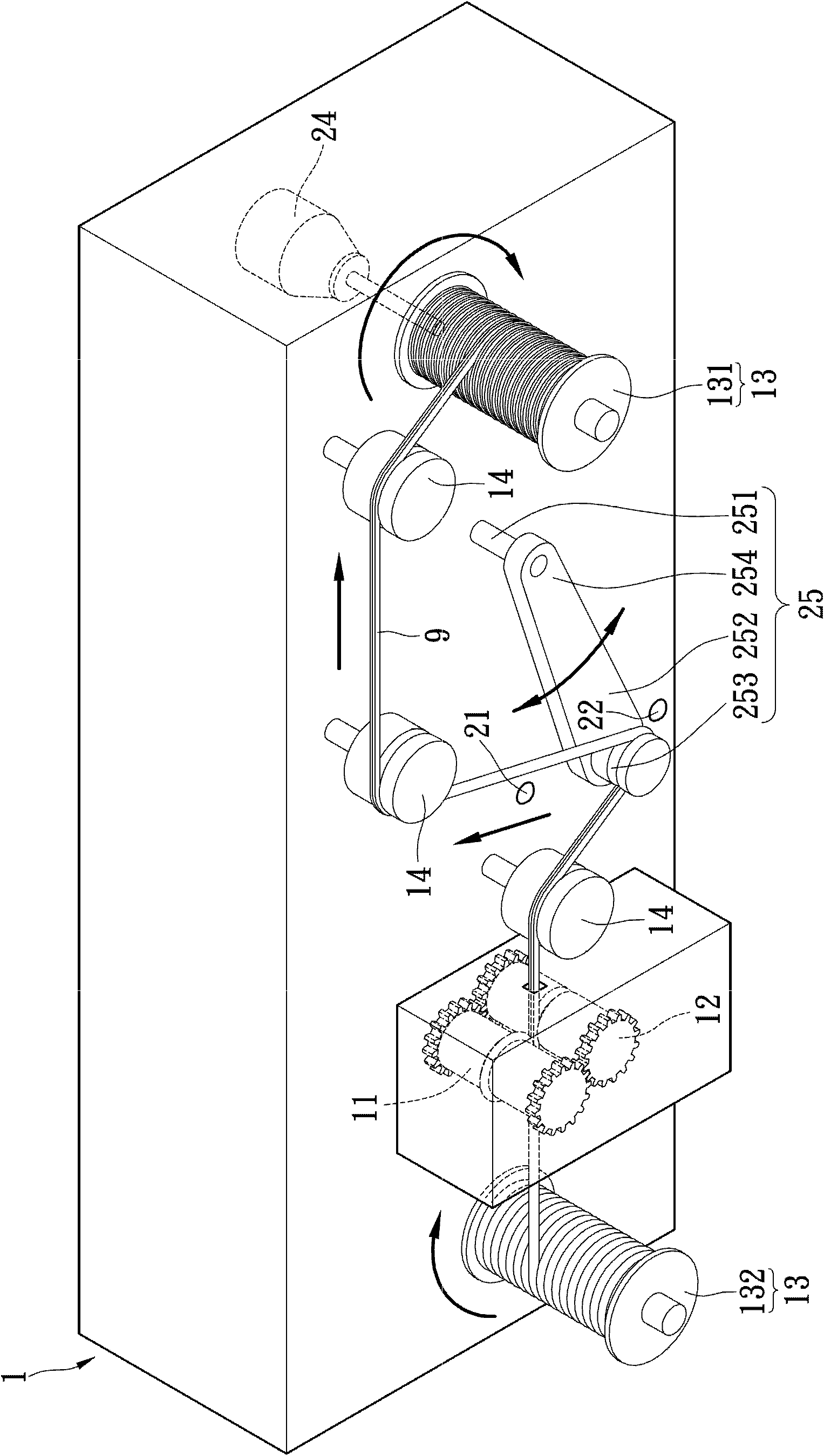
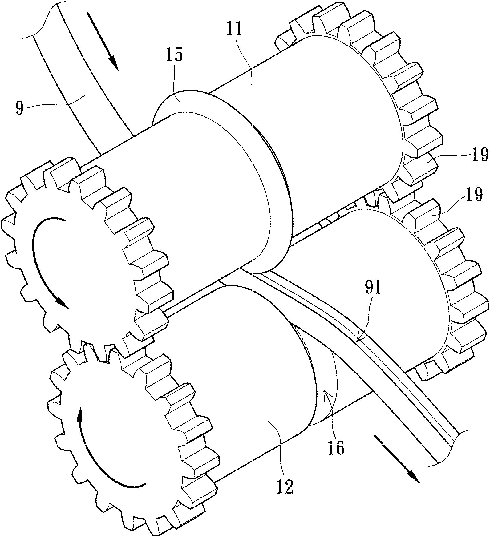
[0054] Please also see Figure 1A and figure 2 , Figure 1A It is a schematic diagram of the appearance of the welding wire cutting machine according to the first embodiment of the present invention, figure 2 It is a structural schematic diagram of the cutter, the first roller and the second roller according to the first embodiment of the present invention. Such as Figure 1A As shown, a welding wire cutting machine 1 is used for cutting a welding wire 9 into a groove 91 (shown in Figure 4 ), so that the groove 91 forms a groove surface. Traditionally, the welding wire 9 is made of soft metal or alloy with a low melting point, so generally speaking, the welding wire 9 is mostly made of tin wire (or tin wire) made of tin metal or tin alloy. The main choice. The wire cutting machine 1 includes a scrolling unit 13 , a cutter 15 , an adjusting arm 25 , a first sensor 21 , a second sensor 22 , a scrolling motor 24 and a plurality of roller units 14 . Wherein, the rolling uni...


PUM


Abstract

The invention provides a bonding wire cutting machine and a bonding wire cutting control method. The bonding wire cutting machine is used for cutting a groove on a bonding wire. The bonding wire cutting machine comprises a rolling unit, a cutter, an adjusting supporting arm and a controller. The rolling unit drives the bonding wire to move axially, and the cutter butts against the radial lateral side of the bonding wire. When the bonding wire moves along the axial direction, the lateral side of the bonding wire is cut by the cutter to form the groove. The adjusting supporting arm is controlled by the controller to adjust the tension of the bonding wire. By means of the bonding wire cutting machine and the bonding wire cutting control method, bonding explosion can be eliminated, working staff can be prevented from being burned, a movable bonding wire can be maintained in a fixed tension range automatically, and falling is avoided.

Description

technical field [0001] The invention relates to a cutting machine, in particular to a welding wire cutting machine which automatically cuts the welding wire into grooves by using a cutter. Background technique [0002] Solder is an important industrial raw material for connecting electronic components in welding lines, and it is widely used in electronics industry, home appliance manufacturing, automobile manufacturing, maintenance industry and daily life. Traditionally, solder is made of solder with a lower melting point, such as solder containing tin-based alloys. In order for factories or maintenance personnel to perform welding operations smoothly during welding, the solder is usually made into a filament (or thread), so it is commonly called "welding wire"; The linear welding wire is dragged and pulled to the place where it needs to be welded. [0003] The welding wire used in standard soldering operations usually has a flux inside it. This flux is composed of rosin a...

Claims


Application Information

Patent Timeline
IPC IPC(8): B21F11/00
Inventor 何长柱
Owner CAL COMP OPTICAL ELECTRONICS SUZHOU
Why Eureka
Try Eureka