
Automatic pipe cutter

A pipe cutting machine, automatic technology, applied in the direction of pipe cutting device, feeding device, positioning device, etc., to achieve the effect of improving work efficiency, remarkable effect and simple structure

Active Publication Date: 2013-08-21
JINHUA YAHU TOOLS
View PDF6 Cites 16 Cited by
  • Summary
  • Abstract
  • Description
  • Claims
  • Application Information

AI Technical Summary

Problems solved by technology

The automatic pipe cutting machine includes the processes of storing, pushing, and cutting. For short-length pipes, it is relatively easy to realize the automation of the above-mentioned processes; There are certain difficulties in the process of feeding

Method used


Image

  • Automatic pipe cutter
  • Automatic pipe cutter

Examples


Embodiment 1

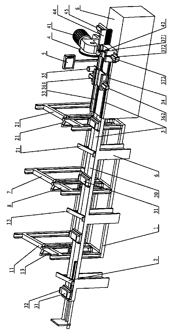
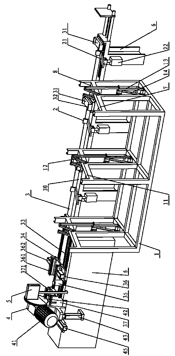
[0030] Such as figure 1 , 2 Shown, a kind of automatic pipe cutting machine comprises frame 6, and frame 6 is provided with material storage device 1, material retrieving device 2, material pushing device 3, cutting device 4, control device 5; Described cutting device 4 is positioned at The end of the frame 6; the control device 5 is fixed on one side of the frame, close to the cutting device 4.

[0031] The storage device 1 includes a storage rack 11, the storage rack 11 is formed by connecting at least two vertical frames side by side, the upper end of the frame is open, and the pipes are placed horizontally on the frame; Swing rod 12, the lower end of the swing rod 12 is hinged with the cross bar, the upper end of the swing rod is connected with the driving mechanism A, and the driving mechanism A is located below the swing rod 12, which is formed by connecting two sets of linkage mechanisms 13 through the upper and lower hinges of the short shaft , And, there is an upwar...


PUM


Abstract

The invention relates to an automatic pipe cutter which is used for cutting pipes and comprises a machine frame. The machine frame is provided with a material storing device, a material taking device, a material pushing device, a cutting device and a control device. The material storing device comprises a material storing frame, and the material pushing device is placed on one side of the material storing frame. The material pushing device comprises a conveying platform, a clamping component which is used for clamping the pipes and a material pushing drive which is used for driving the clamping component. The material taking device is placed between the material storing device and the material pushing device and comprises a material taking plate and a cylinder B which is placed below the material taking device, wherein the material taking device is connected between the material storing frame and the conveying platform, one end of the material taking plate stretches into the edge of the material storing frame, the other end of the material taking plate stretches to the conveying platform, and a piston rod of the cylinder B is connected with the material taking plate. The cutting device is arranged at the end of the machine frame, the material pushing device is placed between the conveying platform and the cutting device. The automatic pipe cutter is high in automation degree, and achieves complete automation in the processes of material taking, material pushing and cutting.

Description

[0001] The invention relates to a cutting machine tool, in particular to an automatic pipe cutting machine for cutting pipes. Background technique [0002] Cutting (cutting) pipe machines are used to cut pipes. The automatic pipe cutting machine includes the processes of storing, pushing, and cutting. For short-length pipes, it is relatively easy to automate the above-mentioned processes; There are certain difficulties in the process of feeding. Contents of the invention [0003] The present invention mainly aims at the problems of taking and pushing materials in the process of automatic cutting of long pipes by the pipe cutting machine, and invents an automatic pipe cutting machine. Complete automation of material and cutting process. [0004] The above-mentioned technical problems of the present invention are implemented through the following technical solutions: an automatic pipe cutting machine, comprising a frame, characterized in that, the frame is provided with a st...

Claims


Application Information

Patent Timeline
IPC IPC(8): B23D21/00B21D43/20B21D43/28B23D33/00
Inventor 王荣民李宝何占丰荆彦鹏聂胤
Owner JINHUA YAHU TOOLS
Learn More