Semi-automatic set screw assembling machine

A set screw, semi-automated technology, applied in metal processing, metal processing equipment, manufacturing tools, etc., can solve the problems of low production efficiency, inaccurate screw thread length, easy to appear slipping phenomenon, etc., to improve production efficiency , The effect of reducing the scrap rate

Active Publication Date: 2013-08-21
GUANGXI UNIV
5 Cites 25 Cited by

AI-Extracted Technical Summary

Problems solved by technology

[0003] The technical problem to be solved by the present invention is to provide a kind of ...

Abstract

A semi-automatic set screw assembling machine comprises a screwing-in device, a support, a screw guiding device, a base plate and a working platform, wherein the support is fixed on one side of the base plate, the working platform is arranged on the upper surface of the base plate, the screw guiding device and the screwing-in device are vertically arranged above the working platform in sequence and respectively connected with the support, the screw guiding device comprises a supporting plate and a guiding sleeve, the upper end of the guiding sleeve is in a cone shape, one end of the supporting plate is fixed on the support through bolts, a cone-shaped hole is formed in the other end of the supporting plate, the guiding sleeve penetrates through the cone-shaped hole and is fixed on the supporting plate, a screwing tool of the screwing-in device, the guiding sleeve and a threaded hole of a piece to be fixed are coaxial, movable inclined plane blocks are arranged on two sides of the working platform, a first limiting wedge and a second limiting wedge are installed between the inclined plane blocks, and the first limiting wedge and the second limiting wedge are in linkage. The semi-automatic set screw assembling machine has certain flexibility, the phenomenon of destroying a screw hole or a screw by screwing is avoided, clamping and uninstalling are synchronous, a screwing length of threads can be adjusted, operation is easy and convenient, production efficiency is high, and an application range is wide.

Application Domain

Metal working apparatus

Technology Topic

Semi automationSet screw +2

Image

  • Semi-automatic set screw assembling machine
  • Semi-automatic set screw assembling machine
  • Semi-automatic set screw assembling machine

Examples

  • Experimental program(1)

Example Embodiment

[0022] The technical scheme of the present invention will be further described below in conjunction with the drawings and embodiments.
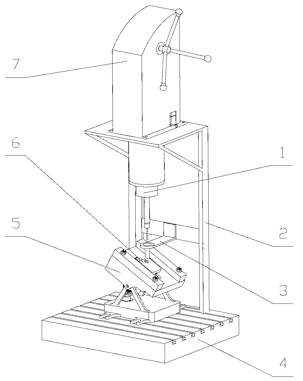
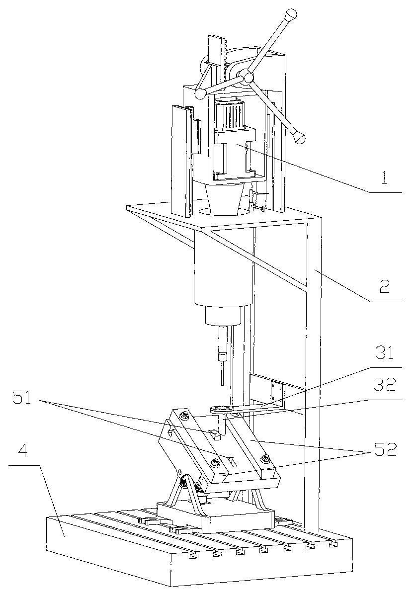
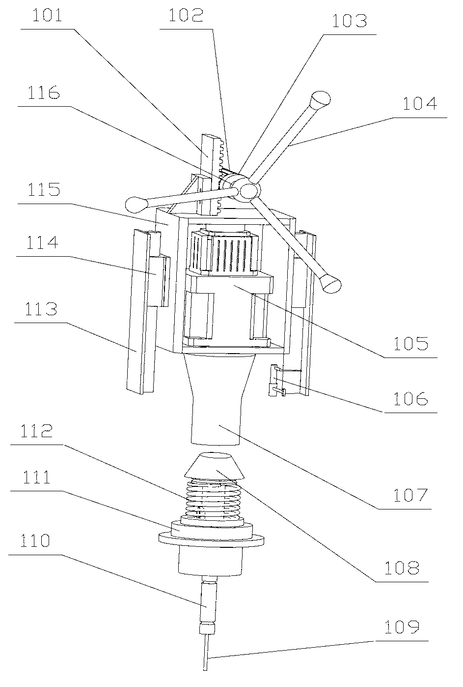
[0023] Such as Figure 1-Figure 4 As shown, the semi-automatic tightening screw assembly machine is composed of a screw-in device 1, a bracket 2, a screw guide device 3, a bottom plate 4, and a workbench 5. The bracket 2 is fixed on one side of the bottom plate 4, the workbench 5 is set on the upper surface of the bottom plate 4, the guide device 3 and the screwing device 1 are vertically arranged above the workbench 5 in turn and are respectively connected with the bracket 2, screwdriver 109, guide sleeve 32 and the screw hole of the part to be fixed 6 are coaxial. There is a T-slot on the bottom plate 4 for fixing the workbench 5, the workbench 5 is divided into upper and lower parts, the lower part is connected with the bottom plate 4 by bolts, and the lower end of the upper part is connected to the lower part by a hinge, and passes through one side The screw adjusts the angle of inclination, the upper surface is equipped with movable inclined blocks 52 on both sides, and two linkage limiting wedges 51 are installed in the middle, which are the first limiting wedges and the second limiting wedges. The left tilt angle of the position wedge is 20-35°, and the right tilt angle is 60-85°; the left tilt angle of the second limit wedge is 70-85°, the right side has no tilt, the second limit The height of the oblique wedge is shorter than that of the first limit oblique wedge; the linkage of the two limit oblique wedges can realize the positioning of the parts to be fixed and the automatic unloading of the installed parts. The screw guide device 3 is located above the workbench 5 and includes a support plate 31 and a guide sleeve 32. One end of the support plate 31 is connected to the bracket 2 by a bolt, and the other end is provided with a tapered hole, through which a tapered guide sleeve 32 passes through The tapered hole. The screwing device 1 is located above the screw guide 3 and includes a screwdriver rotating mechanism, a screwdriver feeding mechanism and a dust cover 7. The screwdriver feeding mechanism is installed in the dust cover 7; the screwdriver rotating mechanism uses a motor 105 as The screw rotation power source realizes the transmission of rotational movement through friction between the tapered hole surface of the output shaft 107 and the tapered shaft surface at the upper end of the transmission shaft 108. The tapered shoulder of the transmission shaft 108 is provided with a groove and fixed in the groove There is a return spring 112. The lower end of the return spring 112 is connected to the sliding bearing 111. The middle section of the transmission shaft 108 is provided with a key groove, which is connected to the sliding bearing 111 through a guide flat key. The sliding bearing 111 is fixed on the sleeve of the bracket 2, and the transmission shaft The lower end of 108 is connected to one end of the flexible rod 110, and the other end of the flexible rod 110 is connected to the screw 109. The screw feed mechanism includes a rack and pinion mechanism, a slide rail mechanism and a screw length adjustment mechanism 106. The rack 101 is connected to the upper part of the motor box 115. The gear 102 is fixed on the gear shaft 116. The gear shaft 116 is from left to right. Equipped with a gear 102, a coil spring 103 and a handle 104, the gear shaft 116 is fixed on the bracket 2, the coil spring 103 is fixed on the bracket 2 through the coil spring box, and the two sliders 114 in the slider rail mechanism are fixed to the motor box 115 On both sides, two guide rails 113 are symmetrically fixed on the bracket 2, and the screw length adjusting mechanism 106 is located directly under the motor box 115 and fixed on the bracket.
[0024] When working, push in the part 61 to be fixed from the left side of the workbench, jam it in the middle of the two limit wedges 51, put the set screw in the guide sleeve 32, rotate the handle 104, and make it through the rack and pinion mechanism. The motor 105 moves down in the direction of the guide rail. The tapered hole surface of the output shaft 107 is in contact with the tapered shaft surface at the upper end of the transmission shaft 108, and friction is generated under the action of the pressure. The transmission shaft 108 rotates under the action of the friction torque, thereby driving the rotation The screw 109 rotates and the screwing device 1 moves downward as a whole. The screw 109 enters the guide sleeve 32, drives the set screw to rotate, and cooperates with the piece 61 to be fixed. When the motor box 115 is in contact with the screwing length adjusting mechanism 106, The precession device 1 cannot continue to move downwards. The operator releases the handle. Under the action of the coil spring 103, the gear 102 reverses, and the rack 101 moves upwards, which drives the motor 105 to rise upward. The gap between the output shaft 107 and the transmission shaft 108 The pressure is reduced, the corresponding friction is reduced, and the transmission shaft 108 stops rotating, the screwing device 1 rises, and an assembly is completed. Take the other part 62 to be fixed and push it in from the left side of the workbench 5. When the first stop wedge is pressed down, the second stop wedge is pressed down, and the part to be fixed 61 that has been assembled slides down. Continue to push the to-be-fixed piece 62 so that it is stuck in the middle of the two limiting diagonal wedges 51 to enter the next assembly cycle.

PUM

PropertyMeasurementUnit
Slope70.0 ~ 85.0deg

Description & Claims & Application Information

We can also present the details of the Description, Claims and Application information to help users get a comprehensive understanding of the technical details of the patent, such as background art, summary of invention, brief description of drawings, description of embodiments, and other original content. On the other hand, users can also determine the specific scope of protection of the technology through the list of claims; as well as understand the changes in the life cycle of the technology with the presentation of the patent timeline. Login to view more.

Similar technology patents

Bamboo batten mat production line

Owner:融安县肖销竹业有限责任公司

Water level sensor

InactiveCN102426042AReduce scrap rateImprove production efficiency and economic benefits
Owner:张家港华峰电接插元件有限公司

Control method for temperature of thermal treatment heating furnace

InactiveCN104328273ASolve temperature deviationReduce scrap rate
Owner:HUBEI JIANGSHAN HEAVY IND

Wire gathering device for brush type connector

Owner:江西嘉宇智能科技有限公司

Classification and recommendation of technical efficacy words

  • Increase productivity
  • Reduce scrap rate

Preparation method of super-retarding type polycarboxylate superplasticizer

ActiveCN103848944AIncrease productivityUniform product
Owner:KZJ NEW MATERIALS GROUP CO LTD

Escapement system

Owner:AIRWAY AUTOMATION

Method for performing positioning chromatography on holographic information and color printing information

InactiveCN101973172APattern registration is accurateReduce scrap rate
Owner:SHANDONG TAIBAO PACKAGING PROD
Why Eureka
Try Eureka