Ventilating system of locomotive electrical chamber with external corridor

A ventilation system and electric room technology, applied to locomotives and other directions, can solve the problems of inability to realize the concentration of ventilation and air intake systems, and achieve the effect of ensuring safe work

Active Publication Date: 2013-08-21
CRRC ZIYANG CO LTD
View PDF6 Cites 8 Cited by
  • Summary
  • Abstract
  • Description
  • Claims
  • Application Information

AI Technical Summary

Problems solved by technology

[0002] The ventilation system of the locomotive electrical room in the traditional outer corridor is designed on the side wall door of the locomotive, and the cooling air for the main generator, traction motor and other electrical equipment is obtained from the scattered side wall doors, which cannot realize the centralized function of the ventilation and air intake system ; At the same time, resistance braking is a kind of electric braking method of locomotives. It uses the reversible principle of DC motor. When braking, the DC motor is changed to DC generator operation, and the kinetic energy of the train is converted into electric energy. On the braking resistor, it is dissipated into the atmosphere in the form of heat energy. Therefore, a corresponding ventilation system is also required to match it for heat dissipation, so as to ensure the safe operation of the resistor braking device.
However, there is no resistance braking device in the electrical room of the locomotive in the traditional outer corridor, so there is no corresponding resistance braking air in and out ventilation system

Method used


Image

  • Ventilating system of locomotive electrical chamber with external corridor
  • Ventilating system of locomotive electrical chamber with external corridor
  • Ventilating system of locomotive electrical chamber with external corridor

Examples


Embodiment Construction

[0012] In order to make the object, technical solution and advantages of the present invention clearer, the present invention will be described in detail below in conjunction with the accompanying drawings and specific embodiments. It should be understood that the specific embodiments described here are only used to explain the present invention, not to limit the present invention.

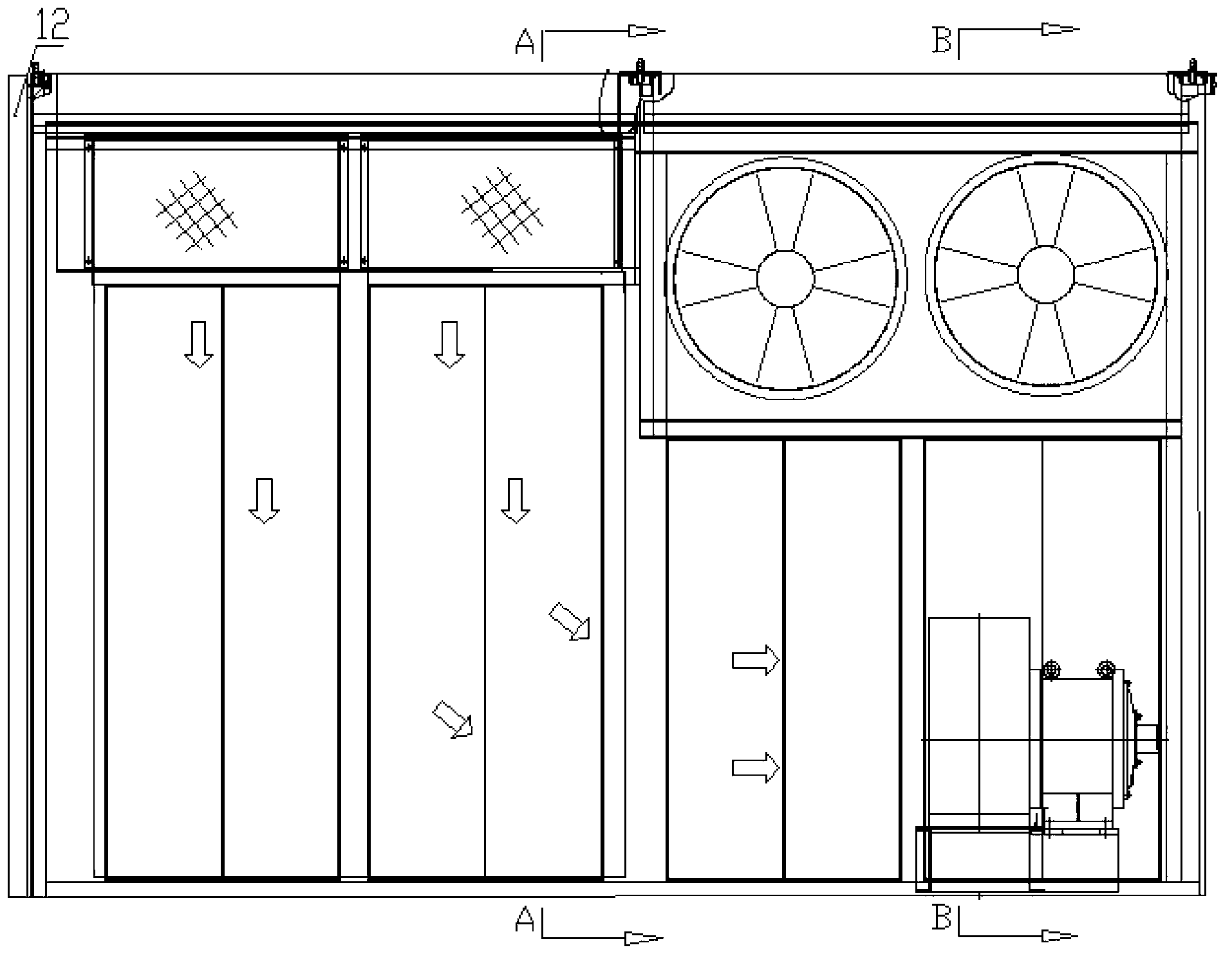
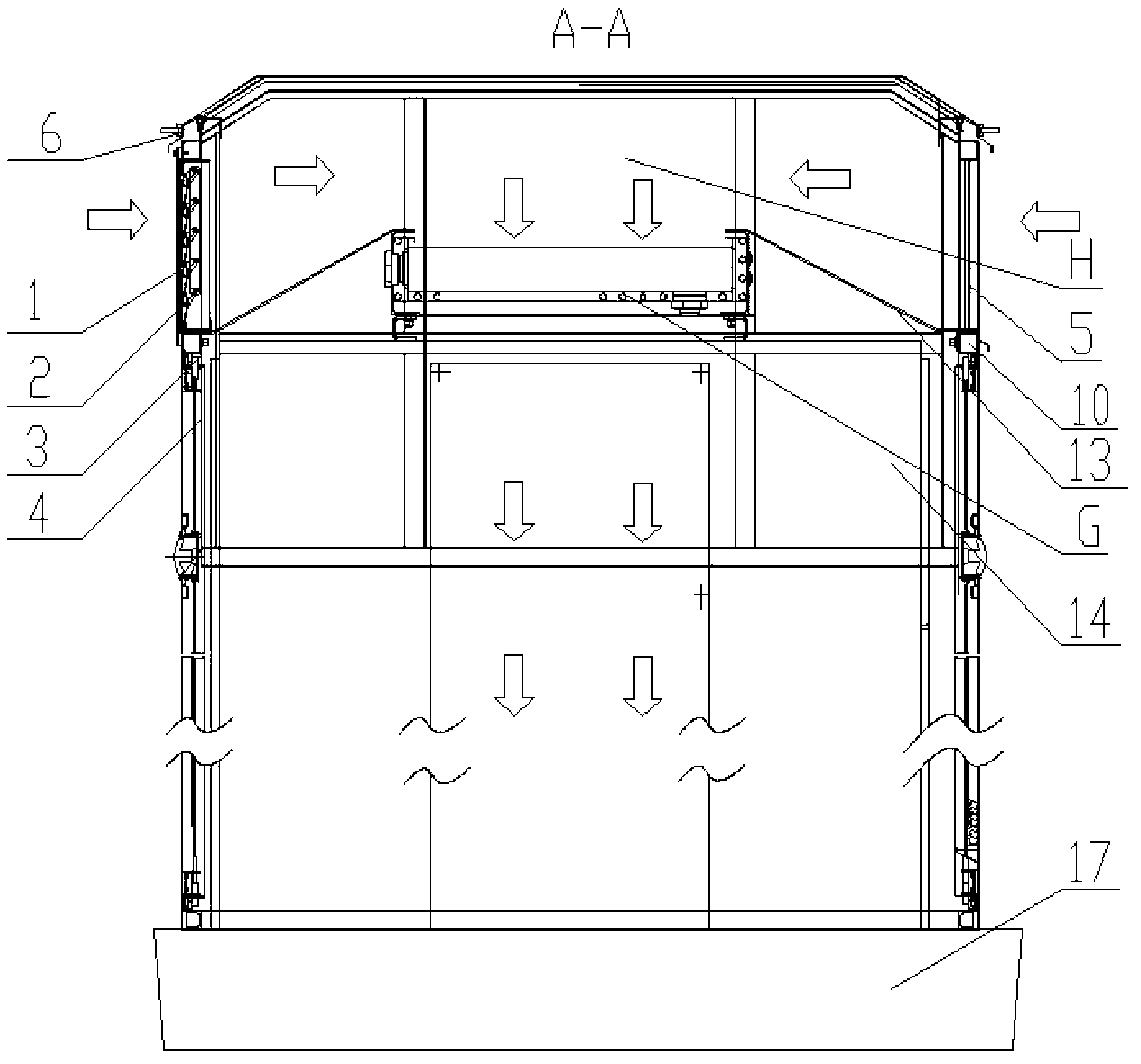
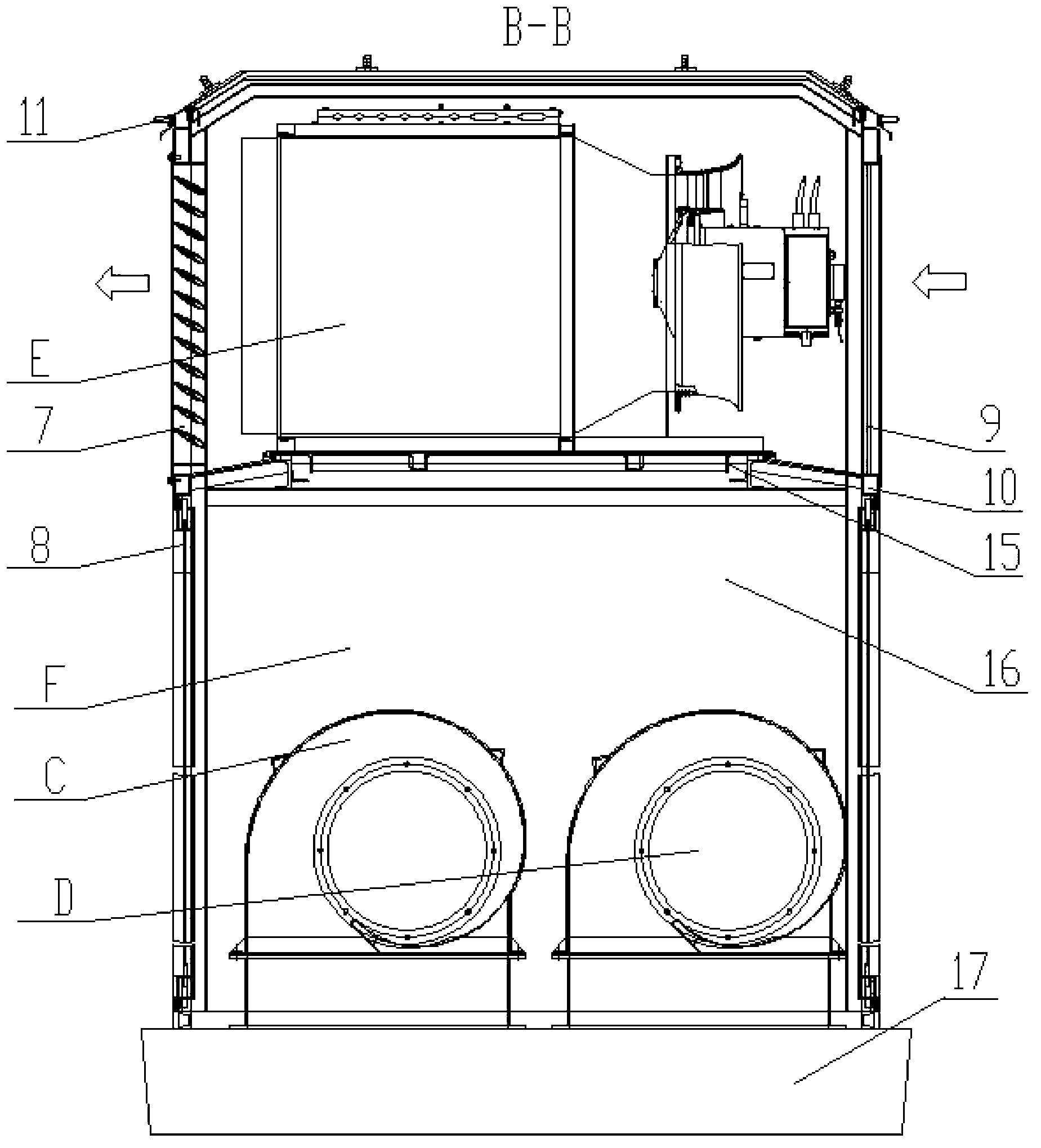
[0013] like Figure 1-Figure 3 As shown, a ventilation system for an electrical room of an outer corridor locomotive is mainly composed of an air chamber F and an air collection chamber H. In order to realize the centralized air intake of the ventilation and air intake system, the above-mentioned air intake air collection chamber H is arranged on the top of the locomotive. 1. The controllable louver assembly 2 community is bolted to the corresponding bolt connection opening of the side wall 1 3; it should be noted that, in order to ensure the normal opening and closing of the louvers of the contr...


PUM


Abstract

The invention provides a ventilating system of a locomotive electrical chamber with an external corridor. The ventilating system mainly comprises an air using cavity (F), an air collecting cavity (H), a resistance braking device air inlet filter screen assembly (9) and a resistance braking device air outlet shutter assembly (7), wherein the air collecting cavity (H) consists of a filter screen assembly (1), a controllable shutter assembly (2), the upper part of a side wall I (3), the upper part of a side wall II (10), an S-type filter screen assembly (5), a ceiling I (6) and an air collecting cavity air channel (13); the air collecting cavity (H) is positioned at the top of a locomotive; and the resistance braking device air inlet filter screen assembly (9) and the resistance braking device air outlet shutter assembly (7) are respectively arranged at the air inlet end and the air outlet end of a resistance braking device (E). The ventilating system realizes centralization of a locomotive air inlet system, and also provides air for circulating cooling and ventilation outlet protection for the resistance braking device (E), so that safety in working of the resistance braking device is ensured.

Description

technical field [0001] The invention relates to the field of locomotive equipment, in particular to a ventilation system for an electrical room of an outer corridor locomotive. Background technique [0002] The ventilation system of the locomotive electrical room in the traditional outer corridor is designed on the side wall door of the locomotive, and the cooling air for the main generator, traction motor and other electrical equipment is obtained from the scattered side wall doors, which cannot realize the centralized function of the ventilation and air intake system ; At the same time, resistance braking is a kind of electric braking method of locomotives. It uses the reversible principle of DC motor. When braking, the DC motor is changed to DC generator operation, and the kinetic energy of the train is converted into electric energy. On the brake resistor, it is released into the atmosphere in the form of heat energy. Therefore, a corresponding ventilation system is also...

Claims


Application Information

Patent Timeline
Patent Type & Authority Applications(China)
IPC IPC(8): B61C17/04
Inventor 李柯
Owner CRRC ZIYANG CO LTD
Why Eureka
Try Eureka