Coupler

A technology of couplings and output shafts, which is applied in the direction of couplings, elastic couplings, rigid shaft couplings, etc., can solve the problem of large influence on the response speed of coupling commutation, complex manufacturing process and assembly process, Problems such as large moment of inertia can be solved to solve the effects of slow commutation response speed, simple manufacturing process, and reduced manufacturing and assembly costs

Inactive Publication Date: 2013-08-21
ANHUI JIANGHUAI AUTOMOBILE GRP CORP LTD
View PDF6 Cites 7 Cited by
  • Summary
  • Abstract
  • Description
  • Claims
  • Application Information

AI Technical Summary

Problems solved by technology

[0006] (1) Since both the active block 1' and the driven block 3' are connected to the corresponding shaft by means of interference fit, they cannot be disassembled;
[0007] (2) The manufacture of the active block 1' and the driven block 3' requires special tooling and fixtures, and the manufacturing process and assembly process are relatively complicated and the cost is high;
[0008] (3) Both the active block 1' and the driven block 3' are made of steel, and the moment of inertia is large, which has a great influence on the response speed of the coupling commutation

Method used


Image

  • Coupler
  • Coupler
  • Coupler

Examples


Embodiment Construction

[0031] Embodiments of the present invention are described in detail below, examples of which are shown in the drawings, wherein the same or similar reference numerals designate the same or similar elements or elements having the same or similar functions throughout. The embodiments described below by referring to the figures are exemplary only for explaining the present invention and should not be construed as limiting the present invention.

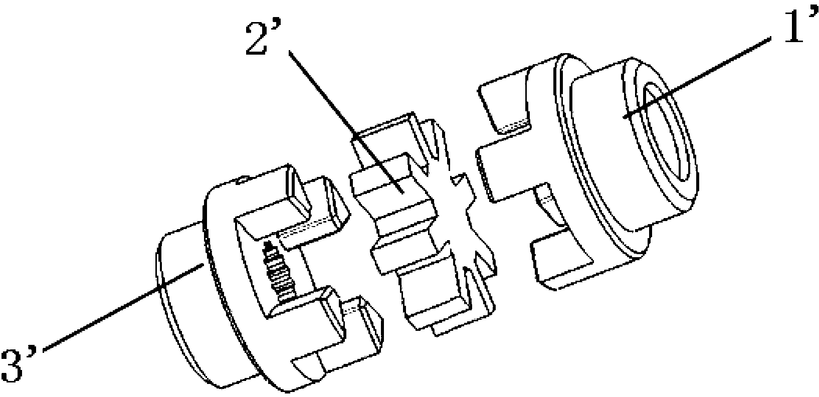
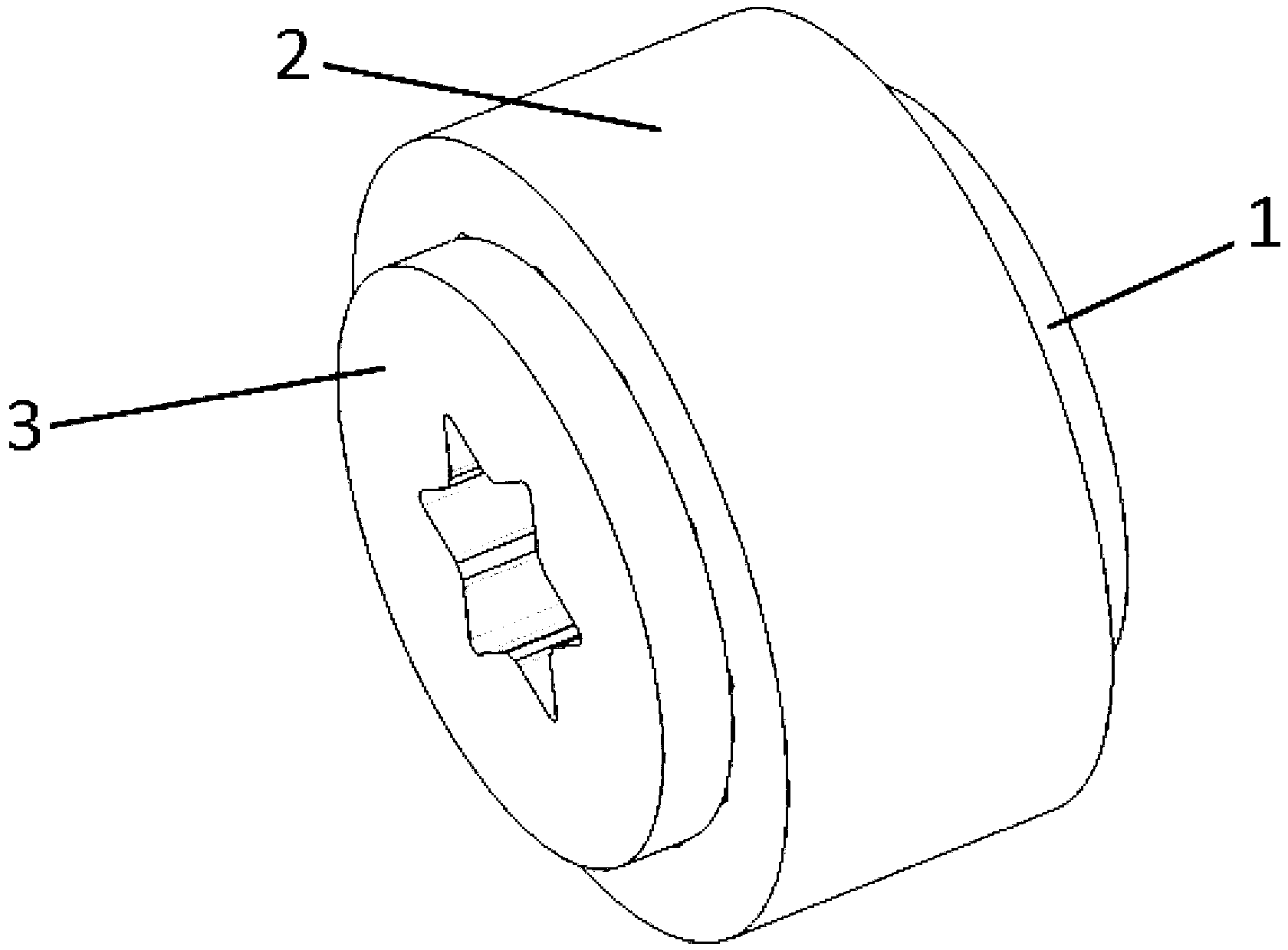
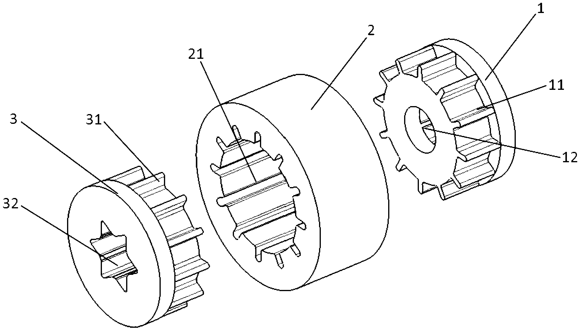
[0032] refer to figure 1 and figure 2 , the coupling includes a driving block 1 , a driven block 3 and a connecting part 2 for connecting the driving block 1 and the driven block 3 . Both the driving block 1 and the driven block 3 are made of nylon material with the characteristics of light weight and high strength. The connecting part 2 is made of one of the following materials: glass fiber, hydrogenated nitrile rubber, polyamide 66. Due to the use of new materials and light weight, the problem of slow reversing response speed of th...


PUM


Abstract

The invention discloses a coupler which comprises a drive block, a driven block and a connection portion used for connecting the drive block and the driven block. The drive block and the connection portion are detachably connected in a motion mutually limiting manner, and the connection portion and the driven block are detachably connected in a motion mutually limiting manner. The drive block and a motor output shaft are detachably connected in a motion mutually limiting manner, and the driven block and a worm shaft of a worm and gear reducer are detachably connected in a motion mutually limiting mode. The coupler is convenient to install, detachable and easy to operate. Due to the fact that a novel material is used, weight is light, the problem of a low reversing response speed of a coupler traditional structure is solved, meanwhile, manufacturing and assembling cost is reduced, and practicality is strong. The drive block and the driven block are identical in structure and simple in manufacturing technology, a mold can be formed in an injection mode at a time, and extra machining is not needed.

Description

technical field [0001] The invention relates to the field of mechanical transmission, in particular to a shaft coupling. Background technique [0002] A coupling is a mechanical part used to connect two shafts in different mechanisms so that they rotate together to transmit torque. [0003] The electric steering column generally adopts a booster mechanism composed of a worm gear reducer, and the booster motor and the worm gear reducer are connected by a coupling. [0004] figure 1 It shows the structural schematic diagram of the coupling that is commonly used to connect the output shaft of the power booster motor and the worm shaft of the worm gear reducer, as shown in figure 1 As shown, the coupling is made up of three parts: the active block 1 ', the damping pad 2' and the driven block 3'. Among them, the active block 1' is processed with four claw blocks, which are connected with the motor output shaft of the booster motor by means of spline press-fitting; the vibratio...

Claims


Application Information

Patent Timeline
Patent Type & Authority Applications(China)
IPC IPC(8): F16D1/04
CPCF16D3/54F16D3/74F16D3/725
Inventor 纪春有唐学东丁玲杨华兴
Owner ANHUI JIANGHUAI AUTOMOBILE GRP CORP LTD
Why Eureka
Try Eureka