Alignment method for liquid crystal VA model

A technology of alignment direction and liquid crystal, applied in nonlinear optics, instrumentation, optics, etc., can solve problems such as waste of opening area, reduced transmittance, and reduced transmittance

Active Publication Date: 2013-08-21
NANJING CEC PANDA LCD TECH
View PDF6 Cites 39 Cited by
  • Summary
  • Abstract
  • Description
  • Claims
  • Application Information

AI Technical Summary

Problems solved by technology

[0011] figure 2 The design shown makes the LCD panel more fully compensated, the viewing angle is larger, and the display quality is better, but it also has corresponding disadvantages: due to more areas, the more black lines are formed, the transmittance will decrease accordingly; and The 8 area is also accompanied by the design of double TFT. It is necessary to divide a pixel into two parts, so that the charging pressure of the pixel is reduced, it can be fully charged, and the display picture is better, but it will waste the opening area and reduce the transmittance.
But this sacrifices part of the transmittance, especially in the case of small pixels, which has a greater impact on the transmittance of the panel

Method used


Image

  • Alignment method for liquid crystal VA model
  • Alignment method for liquid crystal VA model
  • Alignment method for liquid crystal VA model

Examples


Embodiment Construction

[0026] Below in conjunction with accompanying drawing and specific embodiment, further illustrate the present invention, should be understood that these embodiments are only for illustrating the present invention and are not intended to limit the scope of the present invention, after having read the present invention, those skilled in the art will understand various aspects of the present invention Modifications in equivalent forms all fall within the scope defined by the appended claims of this application.

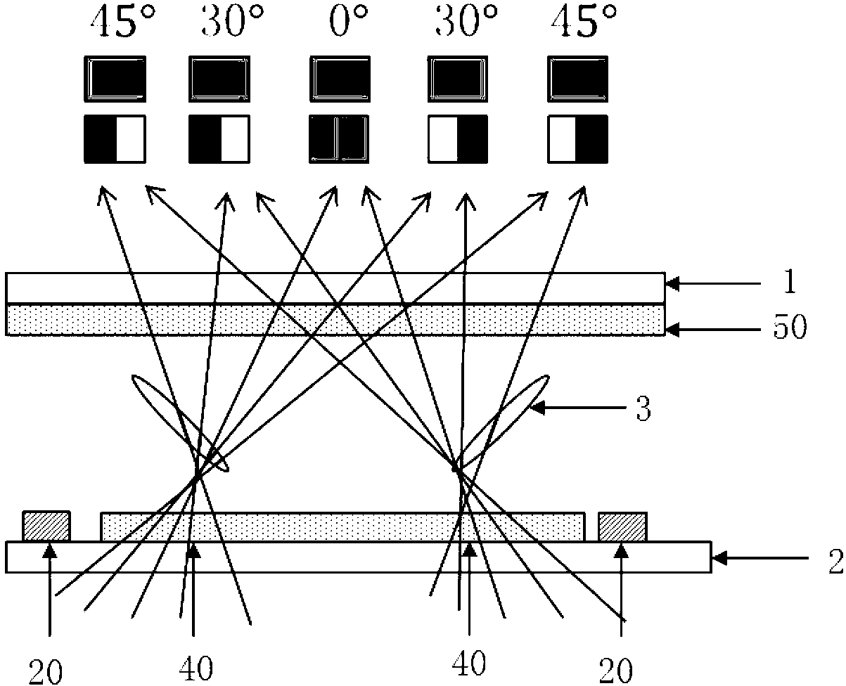
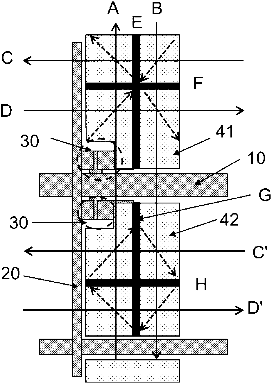
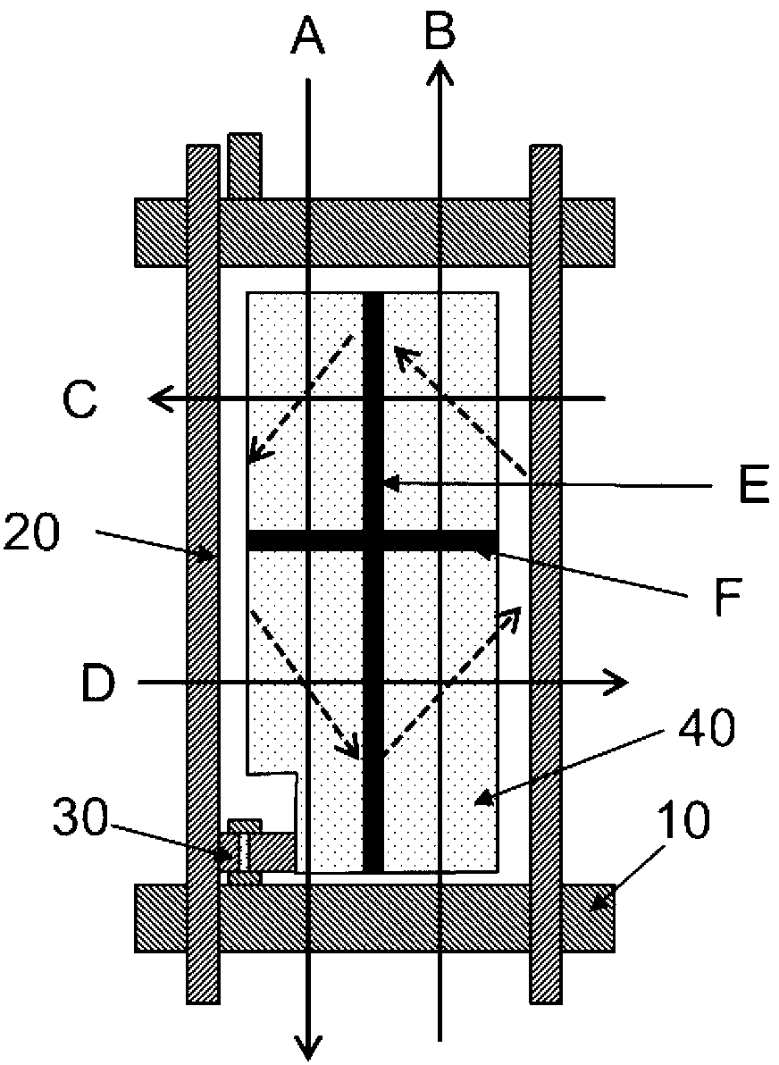
[0027] Figure 4 Be the UV of the liquid crystal display substrate of the present invention 2 A schematic structural diagram of the first embodiment of the alignment method, Figure 4 Shown is a schematic diagram of the structure of the liquid crystal display substrate, also refer to Figure 5 The liquid crystal display substrate includes a TFT-side substrate 2, a CF-side substrate 1, and a liquid crystal 3 sandwiched between the TFT-side substrate 2 and the CF-side su...


PUM


Abstract

The invention provides an alignment method for a liquid crystal VA model. The alignment method comprises the following steps that firstly, a light leakage gap of a UV2A light mask on a TFT side covers a left half part of each sub-pixel unit, a shading strip covers the right half part of each sub-pixel unit, and the alignment direction of the left half parts of the transverse sub-pixel units and the direction of the right half parts of the transverse sub-pixel units are opposite; secondly, a light leakage gap of a UV2A light mask on a CF side covers one integral sub-pixel unit, the light leakage gap of the UV2A light mask on the CF side covers another adjacent integral sub-pixel unit at the lower side, and the alignment directions of the two longitudinally-adjacent sub-pixel units with the same color are opposite. Due to the facts that four areas or eight areas of one sub-pixel in UV2A are parted, and alignment is achieved in two adjacent or four adjacent sub-pixel units jointly, black areas among the four areas of the UV2A are reduced, and an aperture ratio is improved.

Description

technical field [0001] The invention relates to an alignment method of liquid crystal VA mode. Background technique [0002] UV 2 A (Ultra Violet Vertical Alignment) technology is a VA (Vertical Alignment, vertical alignment) panel technology that uses ultraviolet light (UV=Ultra Violet) to align liquid crystals. Its name comes from the multiplication of ultraviolet UV and VA mode of liquid crystal panels. By importing UV 2 After A technology, the slits and protrusions currently used to control the alignment of liquid crystal molecules in VA mode liquid crystal panels can be omitted, so through UV 2 The aperture ratio, contrast ratio, and response speed of A-technology LCD panels can be improved, and the production process can be greatly reduced. [0003] UV 2 The key of technology A is to develop the polymer material used as the alignment film. The main chain of the polymer on the surface of the alignment film is inclined to the direction of ultraviolet (UV) irradiation...

Claims


Application Information

Patent Timeline
IPC IPC(8): G02F1/1337G02F1/139
Inventor 马群刚吴剑龙
Owner NANJING CEC PANDA LCD TECH
Why Eureka
Try Eureka