A battery box for electric power system

A power system and battery box technology, applied in battery pack parts, circuits, electrical components, etc., can solve problems such as difficulty in assembling batteries without interfering with each other, quality problems in parts, and difficulty in connecting terminals, etc. Simple, reduce the market damage rate, and the effect of clear wiring

Active Publication Date: 2015-10-28
JIANGSU XINRI E VEHICLE
View PDF8 Cites 0 Cited by
  • Summary
  • Abstract
  • Description
  • Claims
  • Application Information

AI Technical Summary

Problems solved by technology

[0003] Battery boxes on the market are prone to short circuits, and it is impossible to determine which parts in the battery box have quality problems during maintenance and analysis
After disassembly, it is difficult to connect the corresponding terminals without guidance instructions. All cables must be connected before covering the battery box cover. The cables and battery box cover must be assembled separately, and it is difficult to assemble The wiring, cover, and battery do not interfere with each other, and they are assembled on the whole vehicle. Sometimes the battery is stacked up and down, and the cover is made of pp plastic material, which has a large amount of deformation, and the cover of the box and the battery are suspended. The suspended part is the wiring position of the positive and negative cables. Then, more than half of the batteries of the electric vehicle are placed in an overlapping manner, so that the weight of the upper battery box is directly pressed on the lower battery box cover. The position of the dangling wiring with the battery is pressed inside, and long-term wear and tear will cause problems such as short-circuit of the fragile battery cable.

Method used


Image

  • A battery box for electric power system
  • A battery box for electric power system
  • A battery box for electric power system

Examples


Embodiment Construction

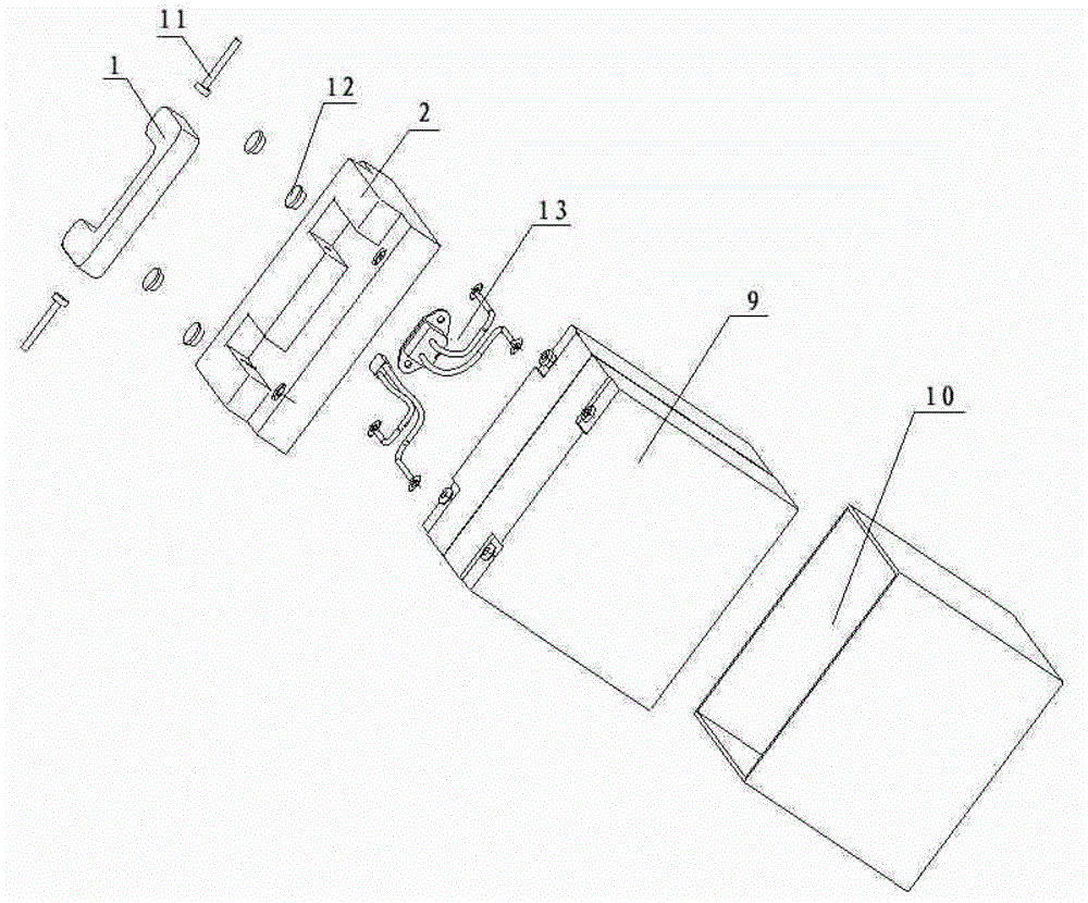
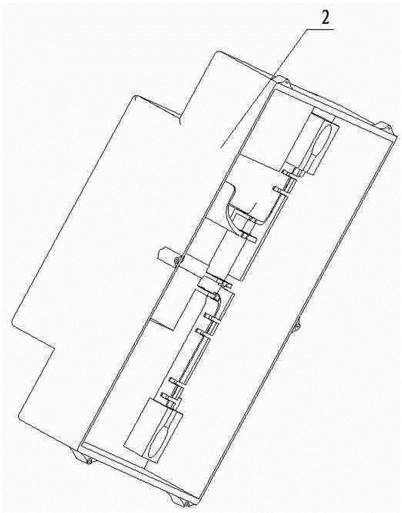
[0019] Figure 1 to Figure 5 As shown, it is a battery box for an electrical power system, including a battery box handle 1 assembled into one, a battery box upper cover 2, a power connection part 13, a battery 9 and a battery box bottom 10; the battery box The upper cover 2 is provided with a card slot structure for ferruling the power connection part 13; the power connection part 13 is detachably snapped into the card slot structure; the conductive screw provided sequentially connects the battery The upper cover terminals uniformly arranged on the box upper cover 2, the power connection terminals of the power connection part 13, and the battery connection terminals of the battery 9 are correspondingly assembled together. Wherein, the battery box handle 1 and the battery box upper cover 2 are assembled together through pins 11 . In addition, a waterproof sealing cover 12 may be provided on the upper cover terminal.

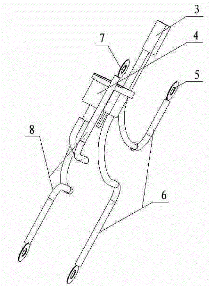
[0020] image 3 As shown, the power connection part 13 in...


PUM


Abstract

The invention discloses a battery case for an electric power system. The battery case comprises a battery case handle assembled integrally, an upper battery case cover, a power supply connecting wire part, a battery and a battery case bottom, wherein a clamping groove structure for clamping the power supply connecting wire part is arranged in the upper battery case cover; the power supply connecting wire part is detachably clamped in the clamping groove structure; and a conductive screw rod sequentially and correspondingly assembles upper cover terminals uniformly distributed on the upper battery case cover, a power supply connecting terminal of the power supply connecting wire part and a battery connecting terminal of the battery. The battery case is mainly applied to the technical field of the safety of electric power systems or current systems, adopts integrated assembly, has a simple structure, is convenient and practical to assemble, and saves cost. A cable in the battery case is clear in routing, wear rates of the battery and the cable are reduced, and the interchangeability is enhanced.

Description

technical field [0001] The invention relates to a battery box used for an electric power system, and belongs to the technical field of electric power systems. Background technique [0002] Most of the battery boxes used in electrical power systems or current safety systems on the market are not particularly well assembled. Connect the two poles to the two outlet sockets, and then press the battery box cover on the upper surface of the battery to fix it. It cannot guarantee whether the wiring state of the wires in the box is reasonable and the bending state of the wires (such as friction, being pressed, short circuit, waterproof) , fever, etc.) cannot be confirmed. In the existing wiring mode, the battery in the battery box must be connected to the cover that has not yet been assembled on the battery box, and finally the battery box cover and the bottom are assembled. Therefore, when the cover is not assembled, the wires on the battery need to be connected in place. When ...

Claims


Application Information

Patent Timeline
Patent Type & Authority Patents(China)
IPC IPC(8): H01M2/20H01M2/10
CPCY02E60/10
Inventor 周勇许广军向龙贤王惠
Owner JIANGSU XINRI E VEHICLE
Why Eureka
Try Eureka