Insertion and extraction force controllable electric connector component and plug thereof

A technology of electrical connectors and plugging force, which is applied to the parts, connections, electrical components and other directions of the connecting device, which can solve the problem of uncontrollable plugging force and achieve the effect of reducing the positioning accuracy requirements

Active Publication Date: 2013-08-21
CHINA AVIATION OPTICAL-ELECTRICAL TECH CO LTD
View PDF7 Cites 11 Cited by
  • Summary
  • Abstract
  • Description
  • Claims
  • Application Information

AI Technical Summary

Problems solved by technology

[0003] The purpose of the present invention is to provide an electrical connector assembly with controllable plugging force, so as to solve the problem that the plugging force of the current in-line electrical connector assembly is uncontrollable

Method used


Image

  • Insertion and extraction force controllable electric connector component and plug thereof
  • Insertion and extraction force controllable electric connector component and plug thereof
  • Insertion and extraction force controllable electric connector component and plug thereof

Examples


Embodiment Construction

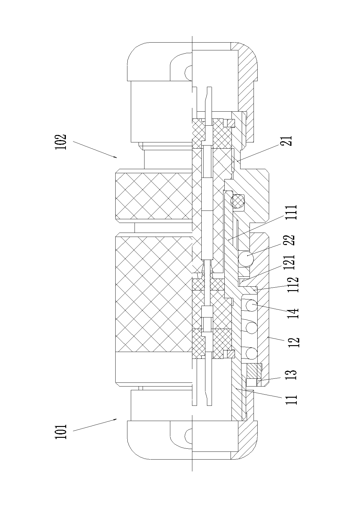
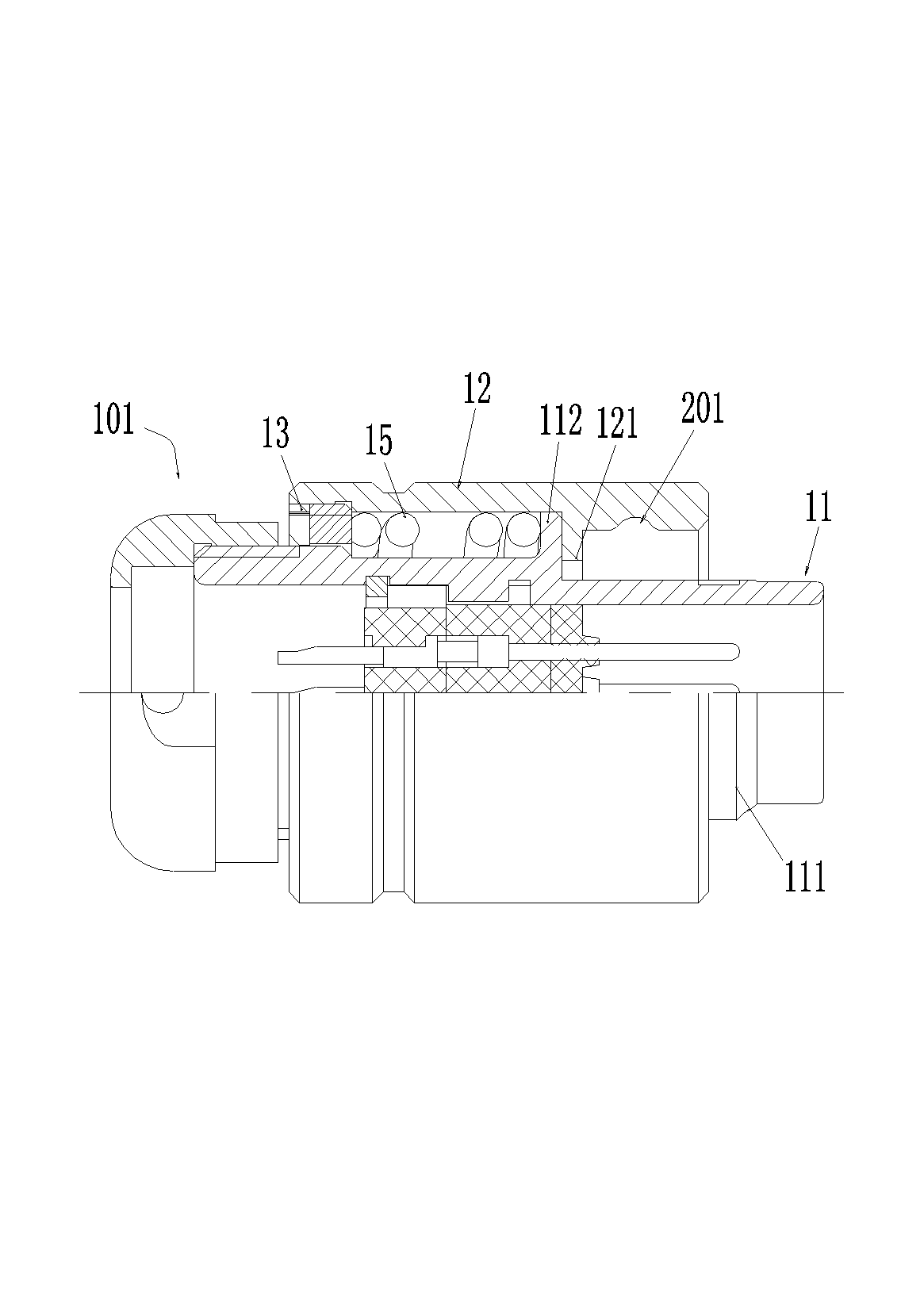
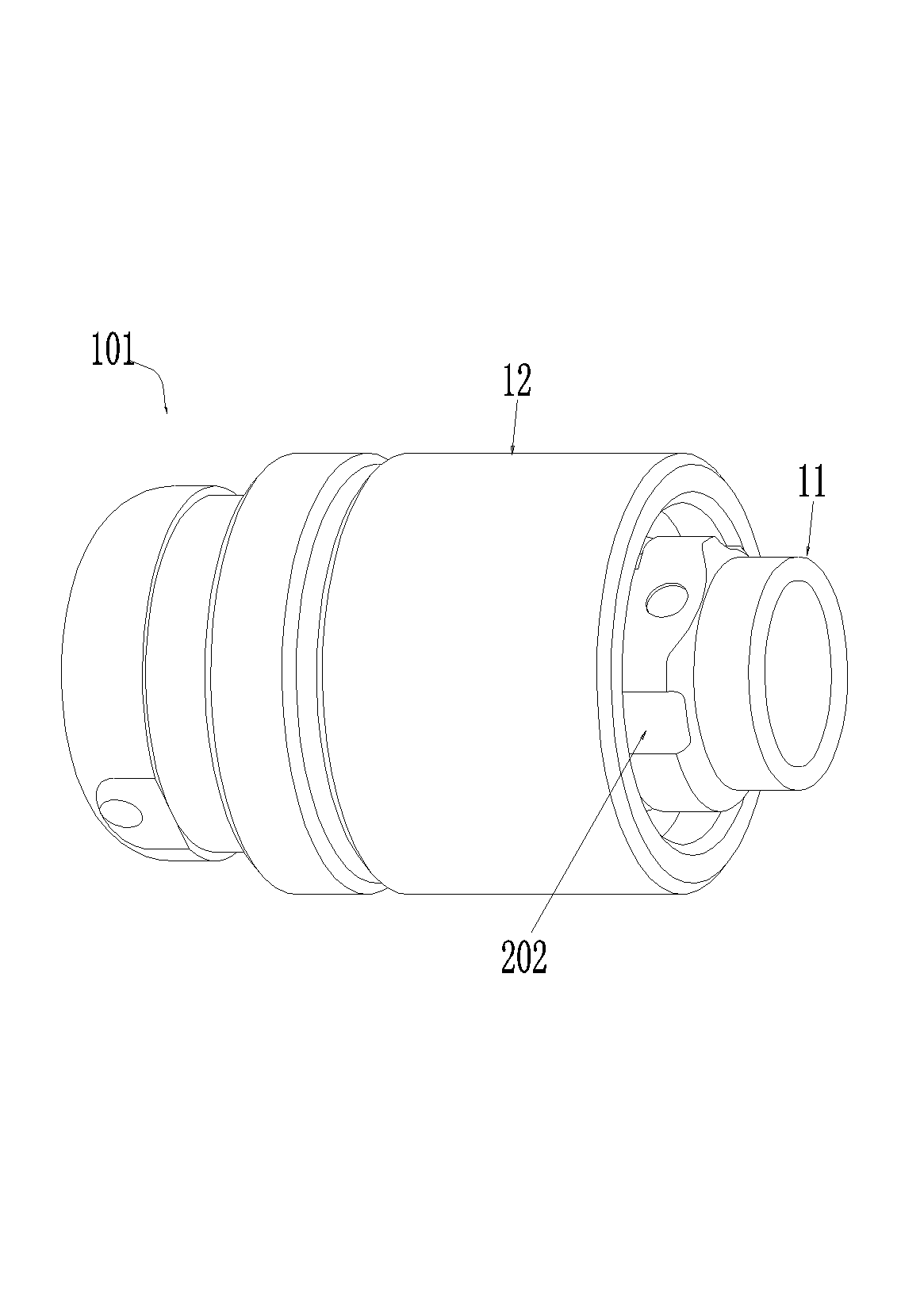
[0025] Embodiments of electrical connector assemblies with controllable insertion force, such as Figure 1-7 As shown, a plug 101 and a socket 102 are included. Each of the plug 101 and the socket 102 has a front end as a plug-in end.

[0026] The plug 101 includes a plug housing 11. The front part of the plug housing 11 has a plug-in section 111, and the plug housing 11 is equipped with a locking cap 12 that can move back and forth. On the body 11, a locking groove 201 is provided on its inner peripheral surface. In this embodiment, the plug housing 11 is provided with an outer convex edge 112 that protrudes toward the peripheral periphery, and the locking cap 12 is located in front of the outer convex edge 112. The side is equipped with a snap ring 13, and an inner convex edge 121 is provided at the rear side of the outer convex edge 112, which is matched with the front and rear of the plug housing 11 through the snap spring 13 and the inner convex edge 121, and the lock gr...


PUM


Abstract

The invention relates to the field of electric connectors, in particular to an insertion and extraction force controllable electric connector component and a plug thereof. The insertion and extraction force controllable electric connector component comprises the plug and a socket, wherein the front end of the plug is used as a pluggable end, and the front end of the socket is used as a pluggable end. A pluggable segment is arranged on the front portion of a plug shell, and a pluggable channel for the pluggable segment to insert is arranged on the front portion of the socket shell. A steel ball is further arranged on the socket shell, and a locking cap capable of moving back and forth is arranged on the plug shell. Locking grooves for the steel ball to be clamped in are formed in the inner wall face of the locking cap, and a push spring is arranged between the plug shell and the locking cap in an ejecting mode. The push spring pushes the locking cap backwards, and a sliding groove corresponding to the steel ball is formed in the outer peripheral face of the pluggable segment of the plug shell. The front end of the sliding groove penetrates through the front end face of the pluggable segment, and a step face is formed on the rear end wall of the sliding groove. The step face is used for blocking the steel ball when the steel ball and the corresponding locking grooves are staggered front-back, and the steel ball can cross the step face backwards when the steel ball is clamped into the corresponding locking grooves. By means of the insertion and extraction force controllable electric connector component and the plug thereof, the problem that insertion and extraction force of an existing direct-plugging type electric connector component is uncontrollable is solved.

Description

technical field [0001] The invention relates to the field of electrical connectors, in particular to an electrical connector assembly with controllable plugging force and a plug thereof. Background technique [0002] In-line electrical connector assemblies have been widely used both in industry and in life. It can be said that the in-line electrical connector assembly is the most widely used electrical connector assembly with the largest number of applications. For example, the simplest Y-shaped plug and panel socket that we often see is a kind of in-line electrical connection assembly. In the existing in-line electrical connector assembly, the insertion and withdrawal force between the plug and the socket is mostly determined by the contact friction force of the contact piece or the locking mechanism, and the friction force has a great impact on the elastic deformation of the elastic piece. Sensitive, not easy to control, after the mechanical life test, the insertion force...

Claims


Application Information

Patent Timeline
Patent Type & Authority Applications(China)
IPC IPC(8): H01R13/639H01R13/631H01R13/64
Inventor 庞卓
Owner CHINA AVIATION OPTICAL-ELECTRICAL TECH CO LTD
Why Eureka
Try Eureka