Supercharge Your Innovation With Domain-Expert AI Agents!

Video driver output amplifier circuit

An amplifier circuit, driving output technology, applied in the direction of improving amplifiers to improve efficiency, etc., can solve the problems of current inversion and increase, and achieve the effect of enhancing the driving ability and increasing the slew rate.

Active Publication Date: 2013-08-21
SHANGHAI BEILING
View PDF5 Cites 5 Cited by
  • Summary
  • Abstract
  • Description
  • Claims
  • Application Information

AI Technical Summary

Problems solved by technology

Therefore, the current flowing through the seventh NMOS tube 18 should be I 7 +I 11 , causing the first node L1 voltage V L1 rises, and at the same time, it will cause the backflow of current at the sixth NMOS transistor 17

Method used


Image

  • Video driver output amplifier circuit
  • Video driver output amplifier circuit
  • Video driver output amplifier circuit

Examples


Embodiment Construction

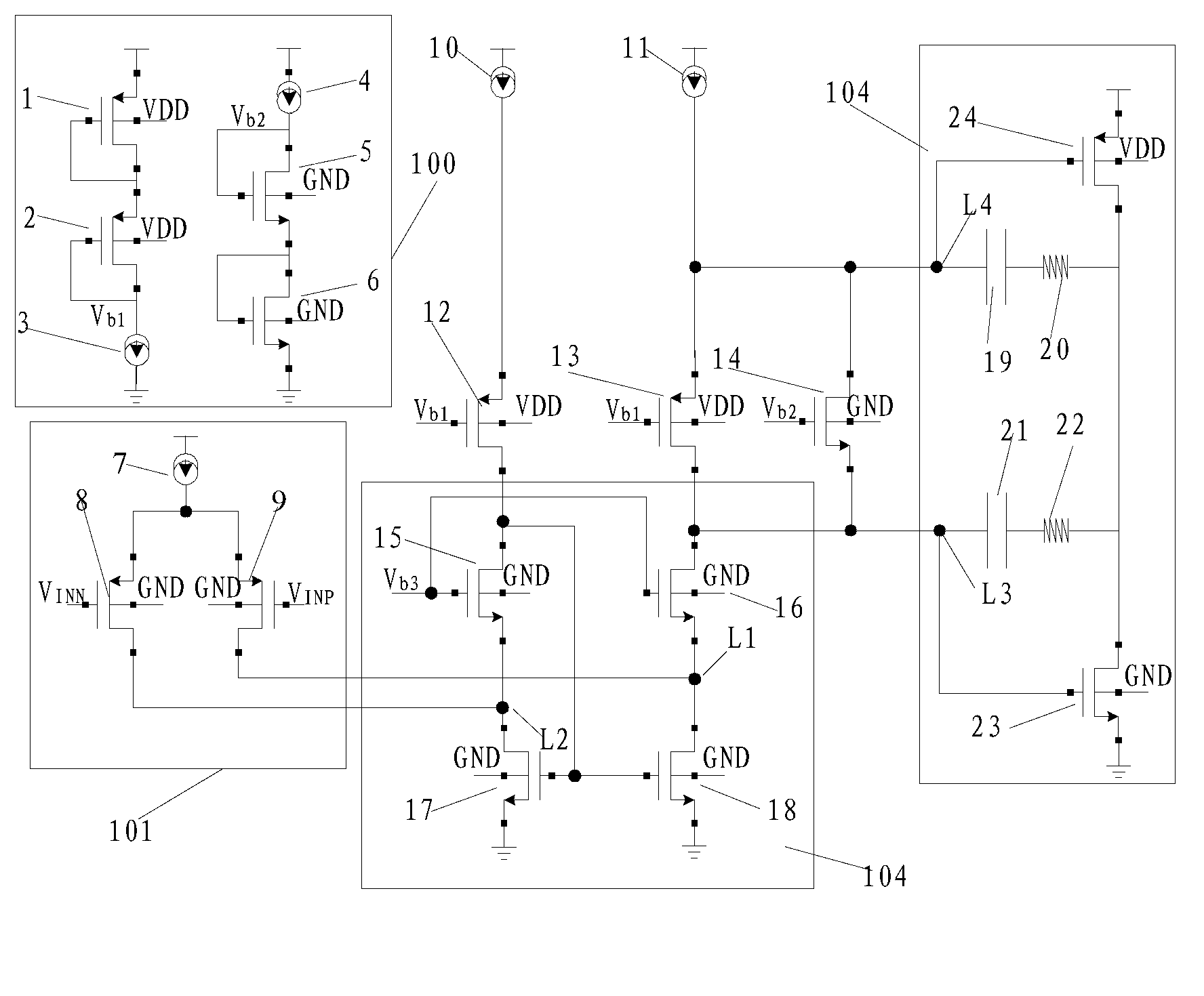
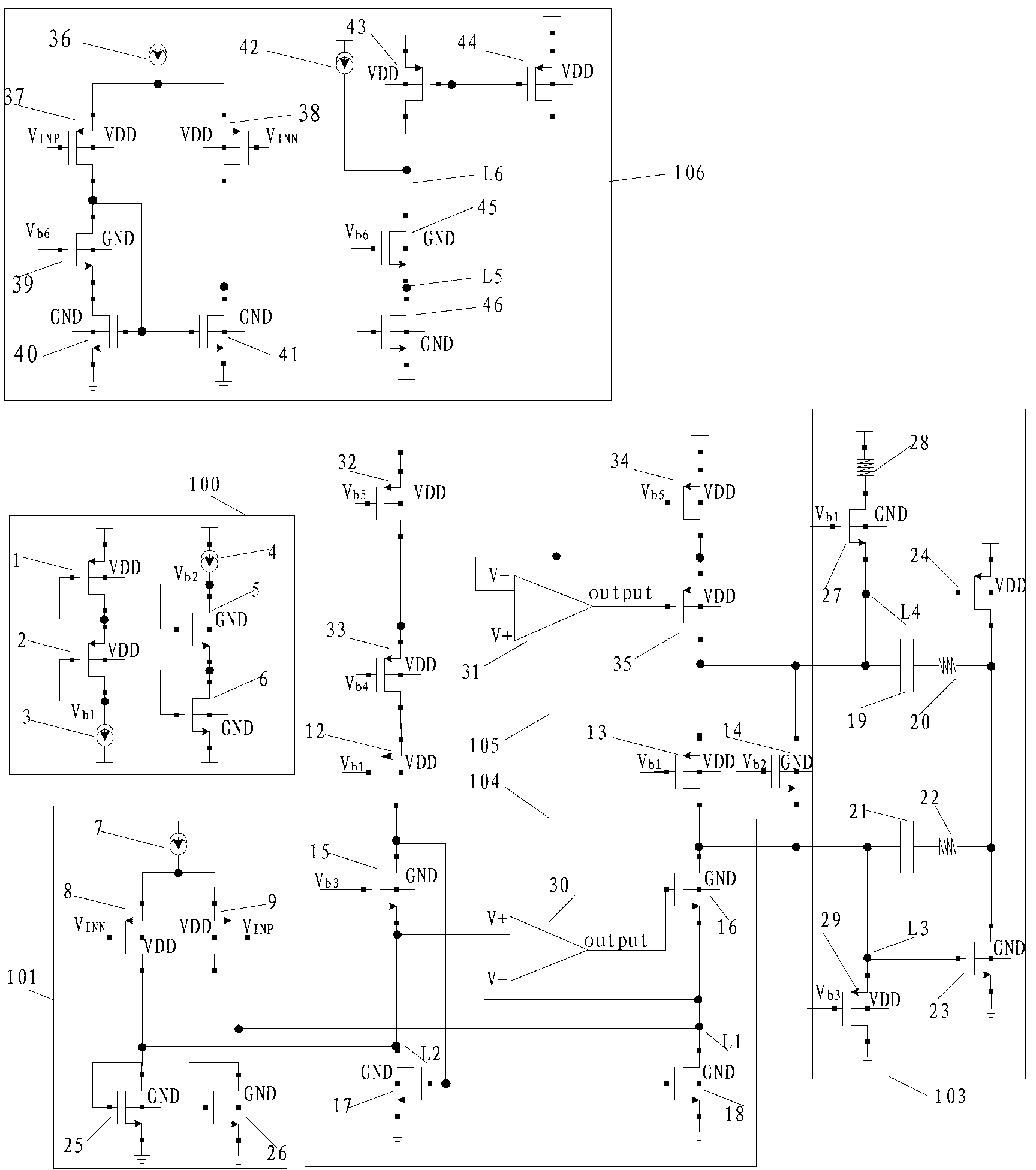
[0046] see figure 2 Referring to Fig. 8, in order to better understand the technical solution of the present invention, the inventors of the present invention will describe in detail below through specific embodiments and in conjunction with the accompanying drawings:

[0047] see figure 2 , a video drive output amplifier circuit of the present invention includes: a bias module 100 , an amplification stage, an output stage 103 , an input stage 101 , and a slew rate control circuit 106 .

[0048] Bias module 100:

[0049] The bias module 100 includes: a first PMOS transistor 1, a second PMOS transistor 2 and a first current source 3 connected in series in sequence. Wherein the first current source 3 is grounded, and the source of the first PMOS transistor 1 is connected to the power terminal. The gate of the first PMOS transistor 1 is connected to the drain of the first PMOS transistor 1, the gate of the second PMOS transistor 2 is connected to the drain of the second PMOS...


PUM


Abstract

The invention discloses a video driver output amplifier circuit which comprises an input stage, an amplification stage, an output stage and a slew rate control circuit, wherein the output stage is an AB class output stage, the slew rate control circuit comprises a cascode input stage formed by a sixth current source, a thirteenth PMOS tube and a fourteenth PMOS tube, a twelfth NMOS tube, a thirteenth NMOS tube, a fourteenth NMOS tube, a seventh current source, a fifteenth PMOS tube, a sixteenth PMOS tube, a fifteenth NMOS tube and a sixteenth NMOS tube, and the thirteenth PMOS tube and the fourteenth PMOS tube correspondingly receive non-inverting input signals and inverting input signals; when the fifteenth PMOS tube is communicated, the sixteenth PMOS tube provides compensation currents for the amplification stage, and driving capacity of the output stage is increased. The video driver output amplifier circuit has the advantages that high gain and loop circuit stability of the video driver output amplifier circuit are guaranteed, and meanwhile the slew rate of the whole circuit is improved.

Description

technical field [0001] The invention relates to a video drive output amplifier circuit in the field of integrated circuits. Background technique [0002] The high-definition video signal has high requirements for the video drive output amplifier circuit. It not only requires the video drive output amplifier circuit to have a strong driving capability, but also requires the video drive output amplifier circuit to have a high slew rate, high gain, low power consumption, and a loop Stablize. current video driver output amplifier circuits such as figure 1 As shown, it includes an input stage 101 , an amplifier stage, an output stage 103 and a bias circuit 100 . [0003] The bias module 100 includes: a first PMOS transistor 1, a second PMOS transistor 2 and a first current source 3 connected in series in sequence. Wherein the first current source 3 is grounded, and the source of the first PMOS transistor 1 is connected to the power terminal. The gate of the first PMOS transis...

Claims


Application Information

Patent Timeline
IPC IPC(8): H03F1/02
Inventor 赵海亮
Owner SHANGHAI BEILING
Features
  • R&D
  • Intellectual Property
  • Life Sciences
  • Materials
  • Tech Scout
  • Unparalleled Data Quality
  • Higher Quality Content
  • 60% Fewer Hallucinations
Learn More