
Electric wrench rack with water discharging groove and applicable to hot-line work

A live work and drainage channel technology, applied in the directions of wrenches, hand-held tools, wrenches, etc., can solve the problems of unfavorable search and placement of other objects, dizziness of operators, affecting the efficiency of live work, etc. Simple structure and high loading and unloading efficiency

Active Publication Date: 2014-12-31
STATE GRID CORP OF CHINA +1
View PDF5 Cites 2 Cited by
  • Summary
  • Abstract
  • Description
  • Claims
  • Application Information

AI Technical Summary

Problems solved by technology

In electric power construction, many tasks require high-altitude operations. When installing an electric wrench socket, you must find the corresponding type of socket in the electric wrench toolbox and insert it firmly; to remove the socket, you need to overcome the huge friction between the wall and the socket. It usually takes two people to complete the work. One person clamps the sleeve with a vise, while the other grabs the electric wrench, and the two pull in opposite directions to make the sleeve disengage from the electric wrench, which may easily cause the bucket arm to shake or even fall off. , which increases potential safety hazards, restricts the operation of electric wrenches at high places, and affects the efficiency of live work; It is a commonly used electric tool, which needs to be picked and placed continuously. The tool box is placed on the bottom of the bucket arm truck. safety, and reduce work efficiency

Method used


Image

  • Electric wrench rack with water discharging groove and applicable to hot-line work
  • Electric wrench rack with water discharging groove and applicable to hot-line work
  • Electric wrench rack with water discharging groove and applicable to hot-line work

Examples


Embodiment Construction

[0025] The technical solution of the present invention will be further described in detail below in conjunction with the accompanying drawings.

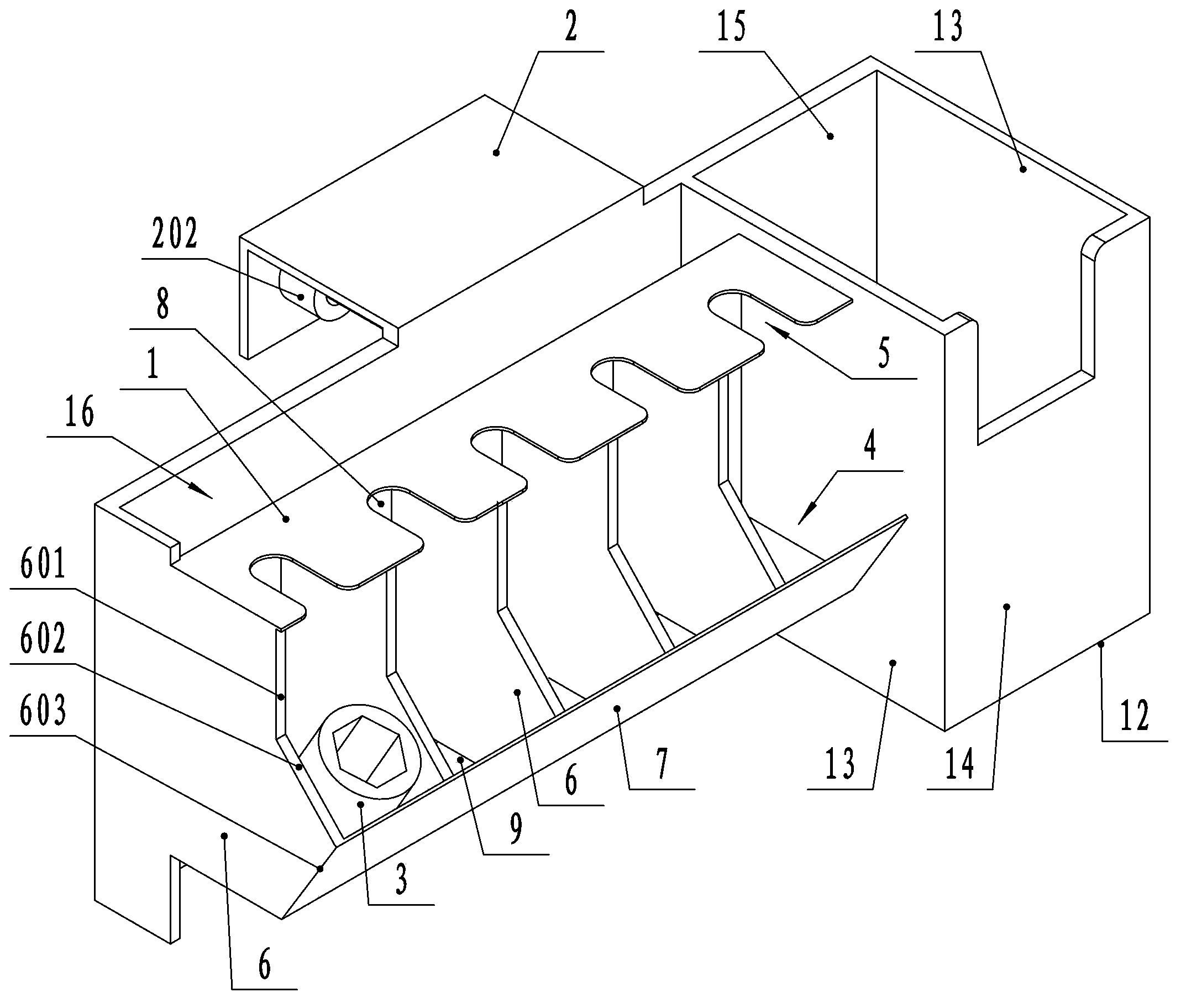
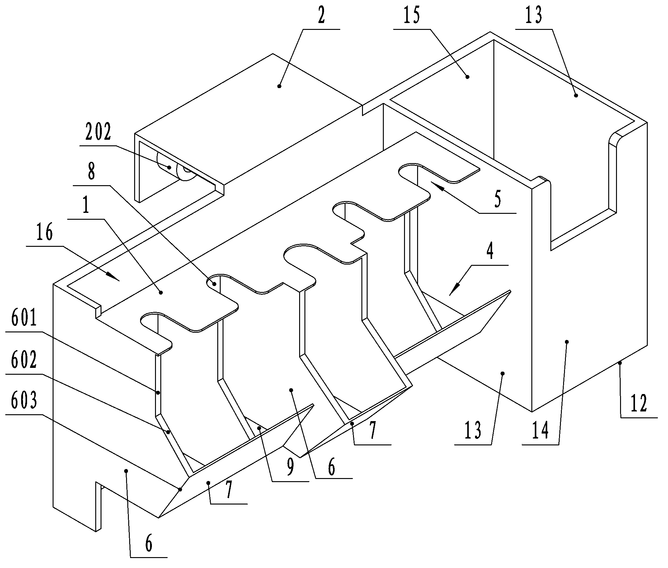
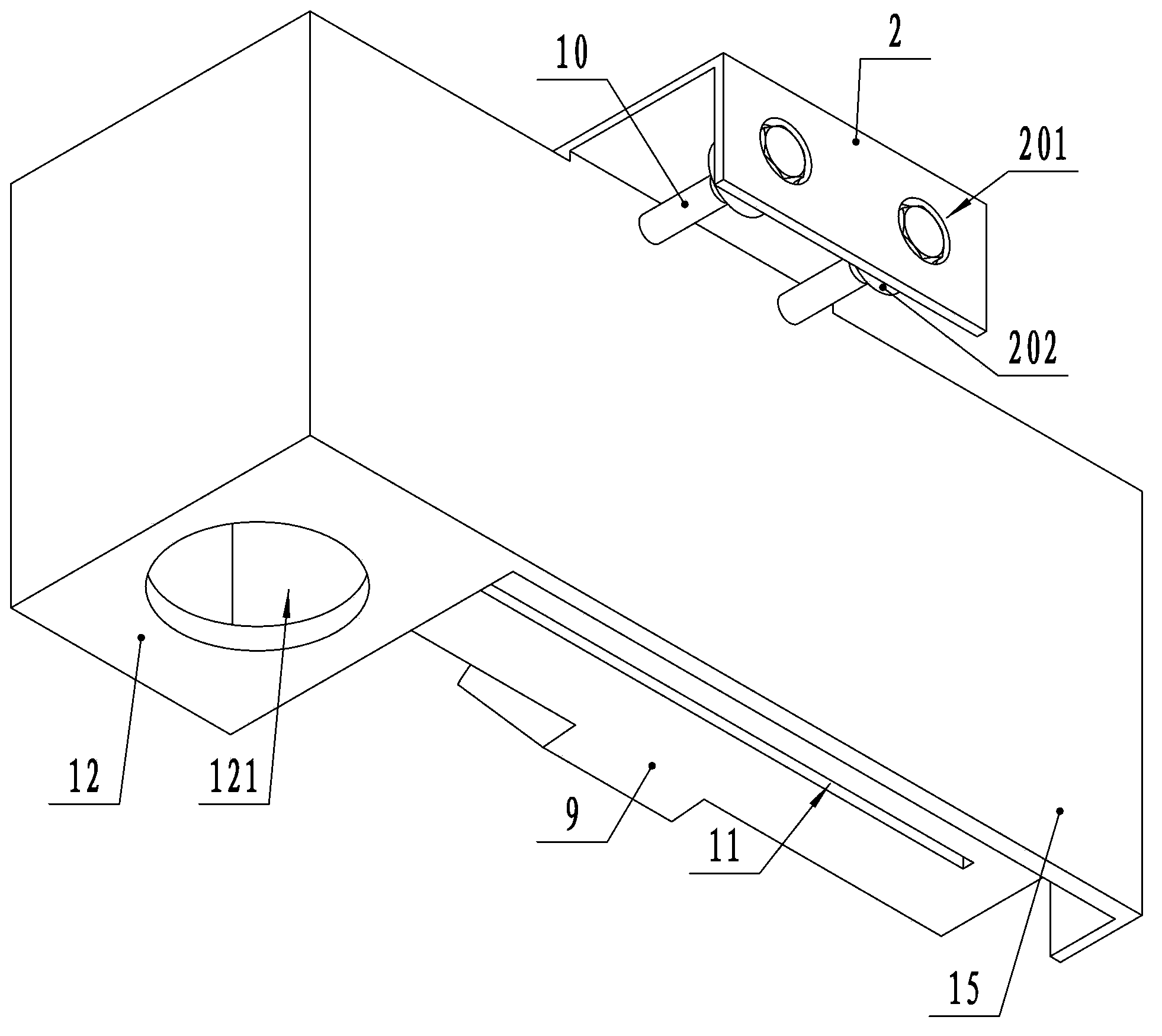
[0026] Such as figure 1 , 2 , 3, the present invention includes a sleeve 3 loader, a wrench placement frame located on one side of the sleeve 3 loader, a fixed frame 2 connecting the sleeve 3 loader and the wrench rack, and the sleeve 3 loader includes a transverse The installed unloading plate 1, the sleeve box located under the unloading plate 1, the rear plate 8 connecting the unloading plate 1 and the sleeve box, the unloading plate 1 has a plurality of "U" shaped slots 5 that can match the rotating shaft of the electric wrench , the opening of the slot 5 is chamfered or rounded, and the sleeve box is provided with a plurality of sleeve accommodation chambers 4 corresponding to the slot 5, the slot 5 communicates with the sleeve accommodation chamber 4, and the unloading plate 1 is connected to the sleeve There is a gap between...


PUM


Abstract

The invention provides an electric wrench rack with a water discharging groove and applicable to hot-line work and relates to an electric wrench sleeve assembling and disassembling device. An electric wrench needs to be matched with bolts with different diameters so that a sleeve needs to be frequently replaced; and the sleeve commonly can be disassembled by two people so that the potential safety hazard is great and the efficiency is low. The electric wrench rack comprises a sleeve assembling and disassembling device, a wrench placing rack and a fixed rack, wherein the sleeve assembling and disassembling device comprises a disassembling plate, a sleeve box and a rear plate; the disassembling plate is provided with a plurality of U-shaped clamping grooves; openings of the clamping grooves are chamfered or rounded; the sleeve box is provided with a plurality of sleeve containing cavities; the clamping grooves are communicated with the sleeve containing cavities; a notch is arranged between the disassembling plate and the sleeve box; the fixed rack is provided with an n-shaped slot; a positioning column is arranged on the inner wall of the slot; the positioning column is provided with a screw hole for penetrating a bolt which is abutted against a bucket arm curb frame; a counter bore is formed on the rear face of the fixed rack; an insulating layer covers the surface of the fixed rack; and a water discharging groove is opened on a bottom plate of the sleeve box. According to the technical scheme disclosed by the invention, the assembling and disassembling efficiency of a sleeve is high; and the electric wrench rack is reliable, is good in working safety and is good in insulation.

Description

technical field [0001] The invention relates to an electric wrench frame. Background technique [0002] The electric wrench has high efficiency in unloading bolts, and it is a commonly used electric tool in electric power construction. In order to match bolts of different diameters, the socket of the electric wrench needs to be replaced frequently, and the phenomenon that the connection between the socket and the socket is often too tight in industrial use. In electric power construction, many tasks require high-altitude operations. When installing an electric wrench socket, you must find the corresponding type of socket in the electric wrench toolbox and insert it firmly; to remove the socket, you need to overcome the huge friction between the wall and the socket. It usually takes two people to complete the work. One person clamps the sleeve with a vise, while the other grabs the electric wrench, and the two pull in opposite directions to make the sleeve disengage from the...

Claims


Application Information

Patent Timeline
Patent Type & Authority Patents(China)
IPC IPC(8): B25B23/00B25H3/04B25B27/06
Inventor 何九葛陈琪明龚志张炎梁本炎赵斌刘能许丽萍张宇
Owner STATE GRID CORP OF CHINA
Learn More