Ultrasonic phased array nondestructive testing method for shafts of recreation facilities

An ultrasonic phased array and non-destructive testing technology, which is applied in the direction of material analysis, measuring devices, and instruments using sound waves/ultrasonic waves/infrasonic waves, can solve problems such as increasing manpower and material resources, and reduce manpower and material resources. The effect of improving detection efficiency

Inactive Publication Date: 2013-08-28
TIANJIN SPECIAL EQUIP INSPECTION INST
View PDF3 Cites 4 Cited by
  • Summary
  • Abstract
  • Description
  • Claims
  • Application Information

AI Technical Summary

Problems solved by technology

There are many types of amusement facilities, and the shapes and sizes of the main shafts on different equipment are not the same, which requires a large number of different types of probes for testing, and processing various shaft test blocks for comparative tests. It is bound to greatly increase the input of manpower and material resources

Method used


Image

  • Ultrasonic phased array nondestructive testing method for shafts of recreation facilities
  • Ultrasonic phased array nondestructive testing method for shafts of recreation facilities
  • Ultrasonic phased array nondestructive testing method for shafts of recreation facilities

Examples


example 1

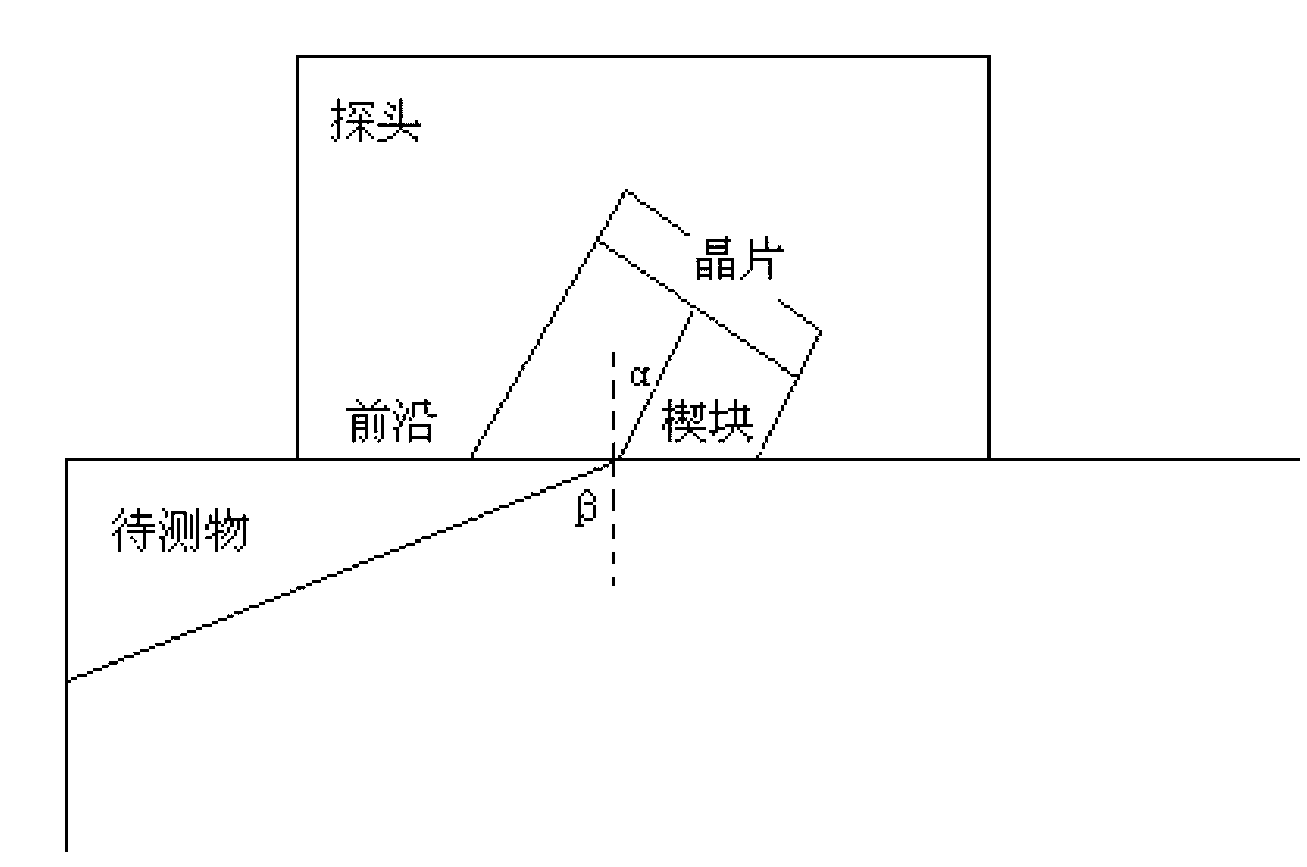
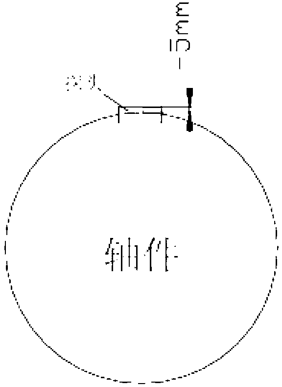
[0023] Select a linear probe with a frequency of 2MHz and 32 chips to detect a shaft with a diameter of 200mm and a length of 1000mm, and detect from the two end faces of the shaft. The sector scanning angle is set to 5-15 degrees, and each side needs to be covered The range of shaft length is 500mm. At the beginning of detection, the relative position of the probe and the shaft is as follows: figure 2 As shown, place the probe at any position on the edge of the end face of the shaft, and align the incident direction of the ultrasonic oblique probe with the outer surface of the shaft instead of the axis. 5mm is the front length of the probe. Move the probe along the circumference to detect Shaft surface defects that are closer to the end face; then move the probe to the center of the shaft for a certain distance, move the probe along the circumference, and continue to detect shaft surface defects that are a little farther from the end face; repeat the above operations until t...

example 2

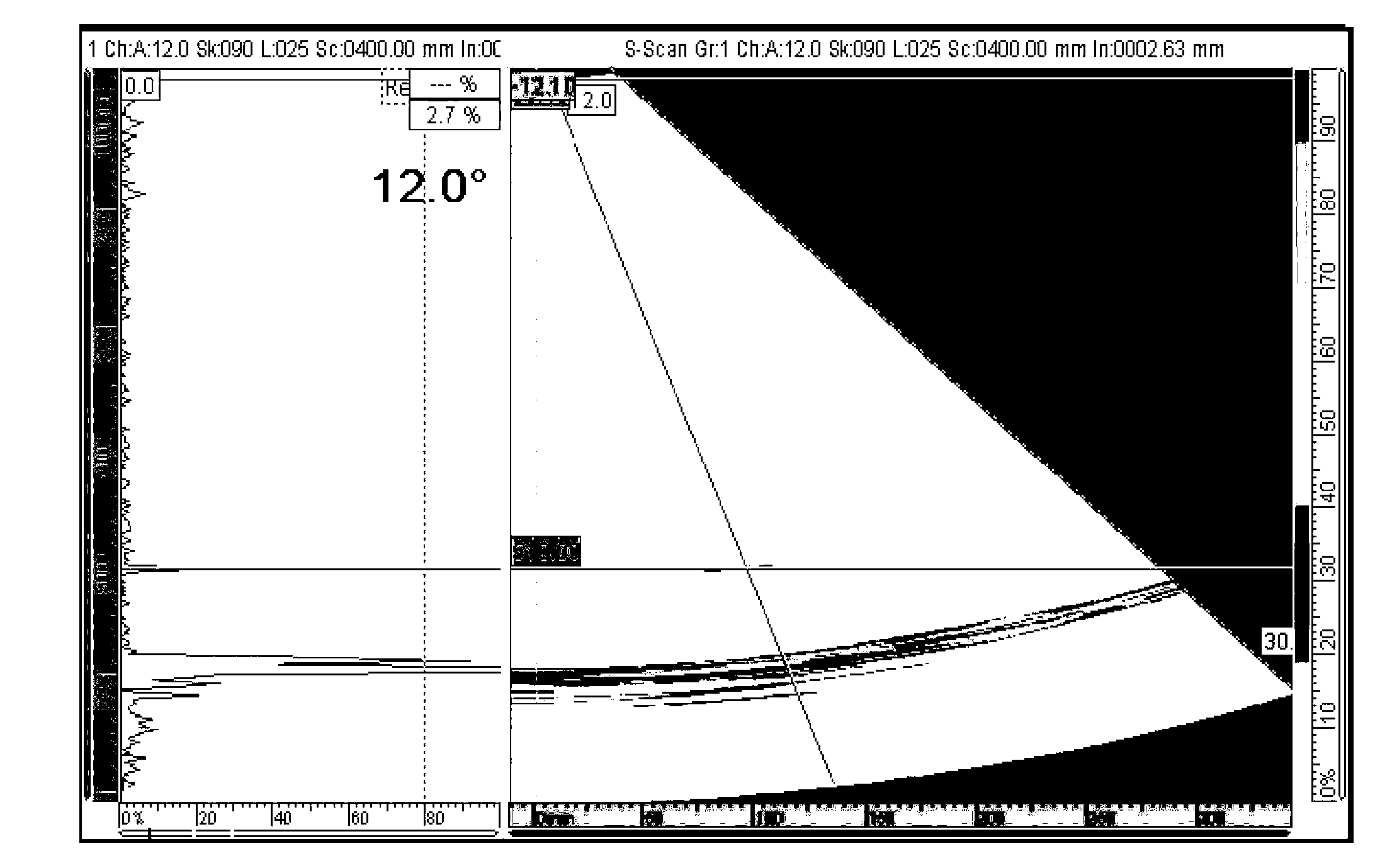
[0025] Select a linear probe with a frequency of 2MHz and 128 chips to detect a shaft with a diameter of 150mm and a length of 800mm, and detect from the two end faces of the shaft. The range of shaft length is 400mm. At the beginning of detection, the probe is placed on the edge of the end face of the shaft, and the probe is moved along the circumference to detect the surface defects of the shaft that are closer to the end face; then the probe is moved to the center of the shaft for a certain distance, and the probe is moved along the circumference to continue to detect defects that are slightly farther from the end face. Shaft surface defects; repeat the above operations until the detection range can cover the shaft surface 400mm long from the end face. It is found that there is a defect at 351mm from one end of the shaft, and the instrument displays the results as follows Figure 4 shown.

example 3

[0027] Select a linear probe with a frequency of 2MHz and 64 chips to detect a shaft with a diameter of 100mm and a length of 500mm, and detect from the two end faces of the shaft. The sector-shaped scanning angle is set to 10-25 degrees, and each side needs to be covered The range of shaft length is 250mm. At the beginning of detection, the probe is placed on the edge of the end face of the shaft, and the probe is moved along the circumference to detect the surface defects of the shaft that are closer to the end face; then the probe is moved to the center of the shaft for a certain distance, and the probe is moved along the circumference to continue to detect defects that are slightly farther from the end face. Shaft surface defects; repeat the above operations until the detection range can cover the shaft surface 250mm long from the end face. It is found that there is a defect at 151mm from one end of the shaft, and the instrument displays the results as follows Figure 5 s...


PUM


Abstract

The invention discloses an ultrasonic phased array nondestructive testing method for shafts of recreation facilities. According to the method, an OmniScan MX instrument is used, a sector scanning angle is set to be less than or equal to 30 DEG, and a linear probe with frequency of 2 MHz and less than or equal to 256 wafers is selected and used for detection from two end faces of a shaft member. The shaft member is divided into corresponding different detection areas along a length direction according to the position of the phased array probe on the end faces of the shaft member and the range of the scanning angle, and the probe is utilized for scanning the areas one by one. Through selection and usage of only one linear probe and utilization of ultrasonic phased array technology, nondestructive testing of shafts with different shapes and sizes can be realized, detection efficiency is improved, the problems that probes of different models are needed for detection of different shafts and different shaft reference blocks have to be arranged for contrast test in traditional ultrasonic testing of shafts are overcome, and investment in manpower and material resources can be substantially reduced.

Description

technical field [0001] The invention relates to an ultrasonic phased array non-destructive testing method for shafts of amusement facilities, belonging to the non-destructive testing technology. Background technique [0002] Amusement facilities such as the Ferris wheel are all rotating motions, and the main shaft is the main force-bearing component. Fatigue damage and wear caused by long-term work are inevitable. Knowing the new defects on the surface of the main shaft is very important for judging whether the amusement facility can operate safely, and the cost of disassembling and testing the main shaft of the amusement facility is very high, so there is no good way to test the main shaft of the amusement facility so far . [0003] At present, domestic research on non-destructive testing of shafts is mainly concentrated in the field of testing axles in the railway industry, and the main method used is small-angle angle probes to detect from the two end faces of the shaft....

Claims


Application Information

Patent Timeline
Patent Type & Authority Applications(China)
IPC IPC(8): G01N29/24
Inventor 牛卫飞姜斌韦晨张晋军王恒萧艳彤王泽军刘怿欢周蕊
Owner TIANJIN SPECIAL EQUIP INSPECTION INST
Why Eureka
Try Eureka