
Anti-electromagnetic-interference pincers-shaped ampere meter device

A clamp ammeter and anti-electromagnetic interference technology, which is applied in the direction of measuring devices, measuring device casings, measuring current/voltage, etc., can solve problems such as inconvenient disassembly and use, and multi-point measurement is not applicable, so as to suppress external electromagnetic interference , improve reliability, and accurately measure the effect

Inactive Publication Date: 2013-08-28
PINGDINGSHAN POWER SUPPLY ELECTRIC POWER OF HENAN
View PDF6 Cites 2 Cited by
  • Summary
  • Abstract
  • Description
  • Claims
  • Application Information

AI Technical Summary

Problems solved by technology

The electromagnetic interference prevention casing grounds the electromagnetic interference protection plate to discharge the excess charge accumulated due to the electromagnetic interference phenomenon, which is not easy to disassemble and use back and forth, and is suitable for short-term and multi-point current measurement in high magnetic field Not applicable

Method used


Image

  • Anti-electromagnetic-interference pincers-shaped ampere meter device

Examples


specific Embodiment 1

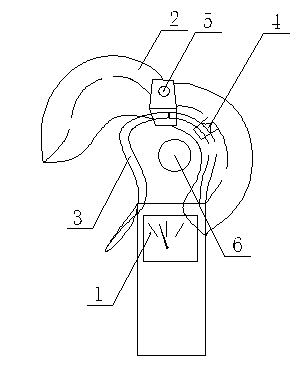
[0012] Such as figure 1 As described above, an anti-electromagnetic interference clamp ammeter device includes a clamp ammeter body 1 and a shielding cover 2, and the shielding cover 2 is provided on the side of the conductive core 3 of the clamp ammeter body 1 .

[0013] The inner side of the shielding cover 2 is provided with an insulating holding card 4 .

[0014] The shielding cover 2 includes two cover units, and the intersection of the two cover units is movably connected.

[0015] A pin shaft 5 is provided at the intersection of the two cover units.

specific Embodiment 2

[0016] Such as figure 1 As described above, an anti-electromagnetic interference clamp ammeter device includes a clamp ammeter body 1 and a shielding cover 2, and the shielding cover 2 is provided on the side of the conductive core 3 of the clamp ammeter body 1 .

[0017] The inner side of the shielding cover 2 is provided with an insulating holding card 4 .

[0018] The shielding cover 2 includes two cover units, and the intersection of the two cover units is movably connected.

[0019] A rivet is arranged at the intersection of the two cover units.

[0020] As in the specific embodiment above, the present invention includes a clamp ammeter body 1 and a shielding cover 2, and the shielding cover 2 is arranged on the side of the clamp ammeter body 1 conductive core 3, which changes the traditional clamp ammeter exposed to a high voltage magnetic field. In this way, the interference to the magnetic conduction circuit of the clamp ammeter body 1 from the strong magnetic field ...


PUM


Abstract

The invention discloses an anti-electromagnetic-interference pincers-shaped ampere meter device which comprises a pincers-shaped ampere meter body and a shielding case. The shielding case is arranged around a magnetic iron core of the pincers-shaped ampere meter body, an insulating holding clamp is arranged on the inner side of the shielding case, the shielding case comprises two case body units, and the two case body units are movably connected at the intersecting portion. Due to the fact that the pincers-shaped ampere meter device comprises the pincers-shaped ampere meter body and the shielding case, and the shielding case is arranged around the magnetic iron core of the pincers-shaped ampere meter body, the phenomenon that a traditional pincers-shaped ampere meter is exposed inside a strong electro-magnetic field is changed, the interference to a pincers-shaped ampere meter magnetic loop from a strong magnetic field of a transformer is effectively avoided, and the traditional pincer-shaped ampere meter can accurately detect and display data, and improves the reliability of the measurement data. Due to the fact that the insulating holding clamp is arranged on the inner side of the shielding case, connecting is reliable, and use is convenient. When the case body units are rotated, an opening can be adjusted. The anti-electromagnetic-interference pincers-shaped ampere meter device is simple in structure, economical, practical, and easy to realize and has good popularization and use value.

Description

technical field [0001] The invention belongs to the technical field of clamp ammeters, in particular to a clamp ammeter device for preventing electromagnetic interference. Background technique [0002] Clamp ammeters are often used in power systems. When in use, the wires in the jaws of the iron core are equivalent to the coils in the measuring mechanism of the electromagnetic system. When the measured current passes through the wires, a magnetic field will be generated in the iron core to magnetize the movable iron piece. , to generate electromagnetic thrust, drive the instrument pointer to deflect, and indicate the magnitude of the measured current. It is easy to use and can directly measure the working current of electrical equipment in operation without disconnecting the power supply and the line, so that it is convenient to know the working status of the equipment in time. However, during high-voltage operations, the high-voltage team is often subjected to interfere...

Claims


Application Information

Patent Timeline
Patent Type & Authority Applications(China)
IPC IPC(8): G01R19/00G01R1/04
Inventor 彭磊亚王迪裴继东姚国茹蒋延磊王学礼银高胜韩向林
Owner PINGDINGSHAN POWER SUPPLY ELECTRIC POWER OF HENAN
Learn More