
Color filter substrate, manufacturing method of color filter substrate and display device

A color film substrate and substrate technology, which is applied in optics, instruments, nonlinear optics, etc., can solve problems such as difficulty in ensuring uniformity and restrictions on the application of color film substrates, and achieve the effect of reducing production costs

Active Publication Date: 2013-08-28
BOE TECH GRP CO LTD +1
View PDF5 Cites 30 Cited by
  • Summary
  • Abstract
  • Description
  • Claims
  • Application Information

AI Technical Summary

Problems solved by technology

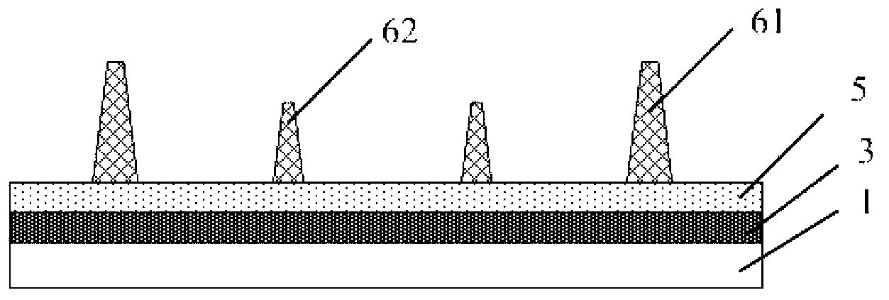
However, according to the current level of photolithography technology and the properties of photoresist, only when the cross-sectional size of the top of the formed spacer is small, its height changes with the size of the exposure area of ​​the mask, such as sub-spacer The height difference design of the main spacer 61 and the auxiliary spacer 62 can only be realized when the cross-sectional size of the top of the object 62 is small (9-11 μm), and its uniformity is difficult to guarantee, and the maximum height difference that can be achieved is less than or equal to 0.5 μm, which brings great limitations to the application of color filter substrates

Method used


Image

  • Color filter substrate, manufacturing method of color filter substrate and display device
  • Color filter substrate, manufacturing method of color filter substrate and display device
  • Color filter substrate, manufacturing method of color filter substrate and display device

Examples


Embodiment 1

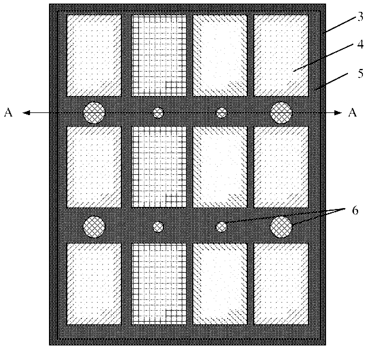
[0039] like image 3 , 4 As shown, a color filter substrate includes a substrate 1, a black matrix 3, a color filter layer 4, and a spacer 6. The black matrix 3 divides the substrate 1 into a plurality of sub-pixel regions distributed in a matrix, so The color filter layer 4 includes N kinds of color photoresist patterns of different colors, N≥3, and the color photoresist patterns of different colors are circularly arranged in discontinuous sub-pixel regions in adjacent N rows / columns, the The spacers 6 include main spacers 61 and sub-spacers 62, wherein the color photoresist patterns in M ​​adjacent sub-pixel regions of a single color in at least one row / column of the color filter layer 4 are also At the same time extending to the top of the black matrix 3 between the corresponding adjacent sub-pixel regions to form a continuous strip color photoresist pattern, and the continuous strip color photoresist pattern corresponds to the top of the black matrix 3. The sub-spacer 62...

Embodiment 2

[0067] The difference between this embodiment and Embodiment 1 lies in that the colors of the color photoresist patterns included in the color filter layer in the color filter substrate of this embodiment are different.

[0068] In this embodiment, the N=4, the color photoresist patterns of different colors include red photoresist patterns, green photoresist patterns, blue photoresist patterns and yellow photoresist patterns, the red photoresist patterns, the The green photoresist pattern, the blue photoresist pattern and the yellow photoresist pattern are arranged cyclically in rows / columns.

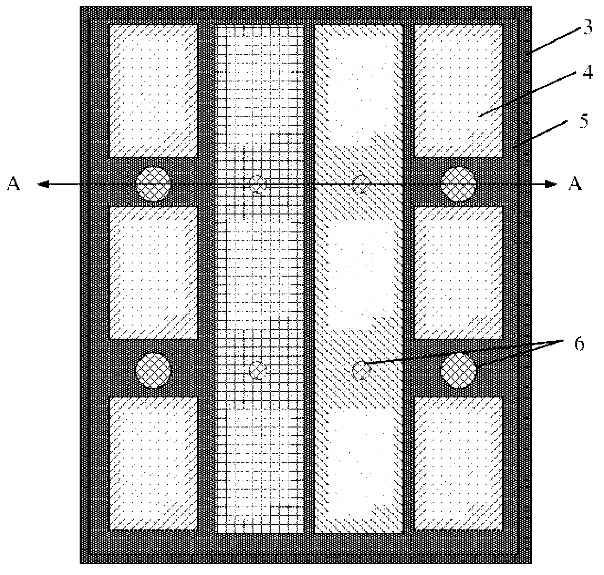
[0069] like Figure 7 , 8 As shown, in this embodiment, the three columns of color photoresist patterns of a single color, the green photoresist pattern, the blue photoresist pattern and the yellow photoresist pattern, are arranged in a continuous strip shape. A sub-spacer 62 that acts as a secondary support is provided above the black matrix corresponding to the yellow photoresist pa...


PUM


Abstract

The invention relates to a color filter substrate, a manufacturing method of the color filter substrate and a display device. The color filter substrate comprises a substrate, a black matrix, a color filter layer and spacers; the substrate is divided into a plurality of sub pixel areas which are distributed in a matrix mode by the black matrix; and the color filter layer comprises N color resist patterns of different colors, the N>=3, the color resist patterns of different colors are circularly arranged in the discontinuous sub pixel areas in neighboring N row / line, at least one row / line of the single-color color resist patterns in the M neighboring sub pixel areas in the color filter layer simultaneously extends above the black matrix between corresponding the neighboring sub pixel areas to form a continuous strip-type color resist pattern, auxiliary spacers are arranged above the portion of continuous strip-type color resist pattern, which corresponds to the black matrix, the main spacers are arranged above a position between the neighboring discontinuous color resist patterns, which corresponds to the black matrix, and the M>=2. The color filter substrate can achieve the height difference control of the main spacers and the auxiliary spacers through a common mask plate and is low in cost.

Description

technical field [0001] The invention belongs to the field of display technology, and relates to a color filter substrate, a preparation method and a display device. Background technique [0002] A liquid crystal display (LCD: Liquid Crystal Display) has become a mainstream product in flat panel displays due to its small size, low power consumption, and no radiation. With the development of display technology, display devices with high transmittance, large size, low power consumption and low cost will become the future development direction. [0003] The existing liquid crystal panel includes a color filter (Color Filter) substrate and an array (Array) substrate, and a liquid crystal is arranged between the two substrates. In order to maintain the cell gap and prevent the liquid crystal from being squeezed and deformed, a spacer is usually provided between the color filter substrate and the array substrate. like figure 1 , 2 As shown, the color filter substrate in the pri...

Claims


Application Information

Patent Timeline
Patent Type & Authority Applications(China)
IPC IPC(8): G02F1/1335G02F1/1333
CPCG02B5/201G02F1/133512G02F1/133514G02F1/13394G02F1/13396
Inventor 黎敏姜晶晶杨同华黄常刚
Owner BOE TECH GRP CO LTD
Learn More