An Electromagnetic Relay with Double Coils

A technology of electromagnetic relays and double coils, which is applied in the direction of electromagnetic relays, electromagnetic relay details, relays, etc., can solve the problems of increased power consumption, difficulty in reducing manufacturing costs, and high cost of enameled wire materials, so as to increase electromagnetic attraction and improve operating performance , Improve the effect of the stress condition

Active Publication Date: 2016-05-11
厦门普利得汽车电子有限公司
View PDF6 Cites 0 Cited by
  • Summary
  • Abstract
  • Description
  • Claims
  • Application Information

AI Technical Summary

Problems solved by technology

[0002] The traditional electromagnetic relay usually sets a coil to cooperate with a yoke and an armature. When the enameled wire is wound on the same skeleton, the diameter of the outer enameled wire becomes larger, and the enameled wire required is longer. The longer the length, the greater the resistance will be, and the power consumption will increase during use. At the same time, due to the high material cost of the enameled wire, it is difficult to reduce its manufacturing cost; on the other hand, since there is only one skeleton, the center of the skeleton can only be installed An iron core, usually the position of the iron core corresponds to the middle position of the inner side of the armature. Theoretically, the armature swings back and forth in cooperation with an electromagnetic attraction force and a pull force generated by a tension spring, but in fact, it is difficult to use only one electromagnetic attraction force It is located in the middle of the inner surface of the armature. When the electromagnetic attraction shifts, the armature may deflect. Sometimes the two elastic control contacts connected to the armature cannot be contacted or disconnected at the same time, which reduces the relay. action performance

Method used


Image

  • An Electromagnetic Relay with Double Coils
  • An Electromagnetic Relay with Double Coils
  • An Electromagnetic Relay with Double Coils

Examples


Embodiment Construction

[0016] The present invention will be described in further detail below in conjunction with the accompanying drawings and specific embodiments.

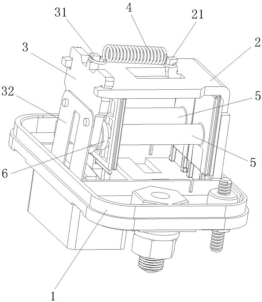
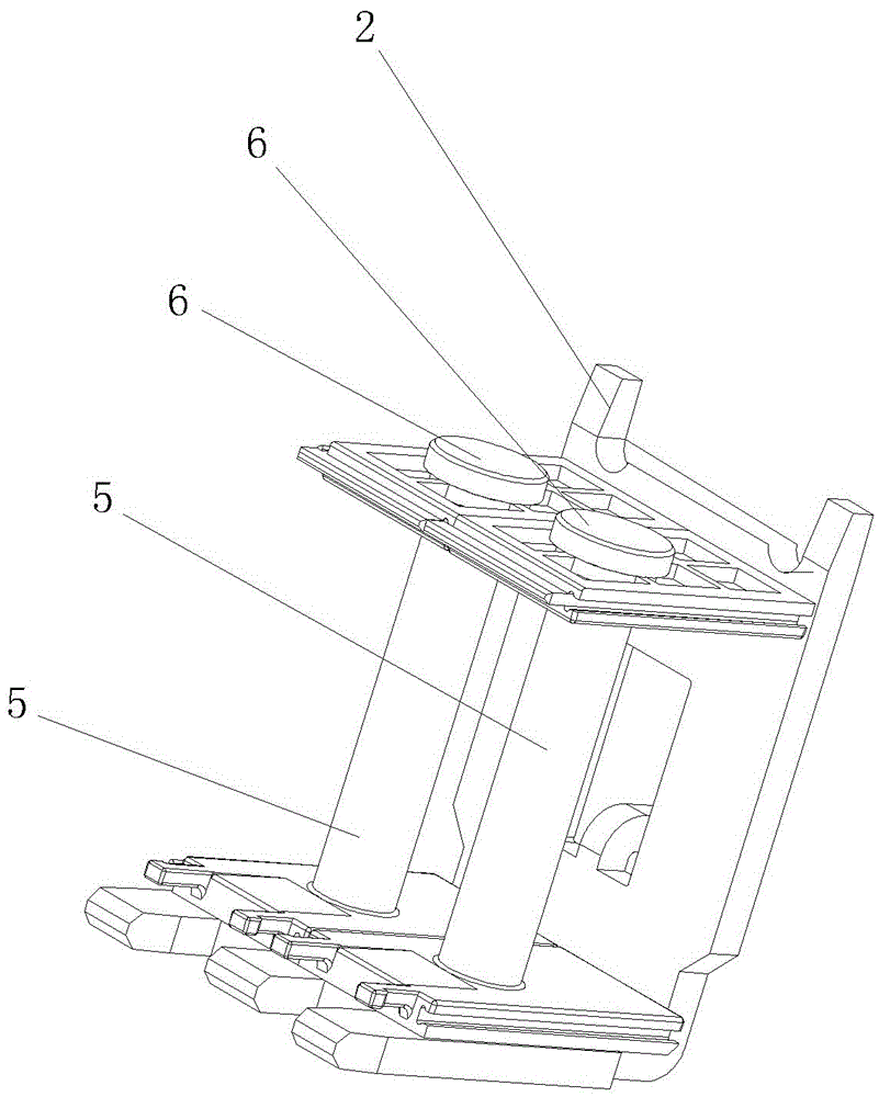
[0017] Figure 1 to Figure 3 As shown, an electromagnetic relay with double coils includes a base 1, an L-shaped yoke 2, and an armature 3. One end of the L-shaped yoke 2 is fixed on the base 1, and the middle and upper part of the armature 3 is overlapped on the On the other end of the L-shaped yoke 2, the armature 3 can swing along the overlapping point. A protrusion 21 is provided in the middle of the upper end surface of the L-shaped yoke 2, and a protrusion 31 is also provided in the middle of the upper end of the armature. The upper end of the armature 3 protrudes. 31 and the protrusion 21 on the upper end surface of the L-shaped yoke 2 are equipped with a tension spring 4, and the middle and lower part of the armature 3 is connected with an elastic contact 32, and the space surrounded by the base 1, the L-shaped yoke 2 and the ...


PUM


Abstract

The invention discloses an electromagnetic relay with double coils, and relates to the technical field of electromagnetic relay manufacturing. The electromagnetic relay comprises a base, L-shaped yoke iron and armature, wherein one end of the L-shaped yoke iron is fixed on the base; the middle upper part of the armature props against the other end of the L-shaped yoke; the armature can swing along an overlapping point; a bulge is arranged at the middle of the upper end surface of the L-shaped yoke; a spring is mounted between the upper end of the armature and the bulge on the upper end surface of the L-shaped yoke iron; an elastic contact is connected with the middle lower part of the armature; two skeletons are mounted in parallel in a space formed by the base, the L-shaped yoke iron and the armature in a surrounding manner; windings are wound on the two skeletons and are connected in series; an iron core is respectively mounted at the middle of each skeleton; and the positions of the two iron cores, near one end of the armature, are corresponding to the position of the inner side surface of the armature. According to the electromagnetic relay, the usage amount of winding enameled wires is reduced effectively, so that the power consumption and the manufacturing cost of the relay are lowered; the action reliability of the armature is improved; and the working performance of the relay is ensured.

Description

technical field [0001] The invention relates to the technical field of electromagnetic relay manufacturing, in particular to an electromagnetic relay with double coils. Background technique [0002] The traditional electromagnetic relay usually sets a coil to cooperate with a yoke and an armature. When the enameled wire is wound on the same skeleton, the diameter of the outer enameled wire becomes larger, and the enameled wire required is longer. The longer the length, the greater the resistance will be, and the power consumption will increase during use. At the same time, due to the high material cost of the enameled wire, it is difficult to reduce its manufacturing cost; on the other hand, since there is only one skeleton, the center of the skeleton can only be installed An iron core, usually the position of the iron core corresponds to the middle position of the inner side of the armature. Theoretically, the armature swings back and forth in cooperation with an electromag...

Claims


Application Information

Patent Timeline
Patent Type & Authority Patents(China)
IPC IPC(8): H01H50/44
Inventor 陈长桥
Owner 厦门普利得汽车电子有限公司
Why Eureka
Try Eureka