Eureka AIR delivers breakthrough ideas for toughest innovation challenges, trusted by R&D personnel around the world.

Measurement circuit

A technology for measuring circuits and paths, used in electrical components, electronic commutators, motor control, etc., and can solve complex problems

Active Publication Date: 2013-08-28
TRW LIMITED
View PDF5 Cites 3 Cited by
  • Summary
  • Abstract
  • Description
  • Claims
  • Application Information

AI Technical Summary

Problems solved by technology

In the applicant's later application WO2008 / 139718, a sample and hold circuit is used to remove the DC offset, but this solution is also necessarily complicated

Method used


Image

  • Measurement circuit
  • Measurement circuit
  • Measurement circuit

Examples


Embodiment Construction

[0029] The present invention can be used with electric motors in a variety of applications, however, examples of electric motors used in steering systems are described below. The steering system includes a steering rack configured to move side to side to control the angle of the vehicle's front wheels. The rack is connected by a steering shaft to the steering wheels, which can be steered by the driver to cause the rack to move. To assist the driver with wheel steering, the electric motor is connected to a shaft (or rack) through a gearbox. This is often referred to as a power assist system. In an alternative, power assistance may be provided hydraulically by connecting a hydraulic circuit and a bilateral piston within a movable cylinder to the rack in known manner. Hydraulic fluid is pumped around the hydraulic circuit in a known manner by using a pump driven by an electric motor. Therefore, the electric motor is the main power source for auxiliary use. It's called electro...


PUM


Abstract

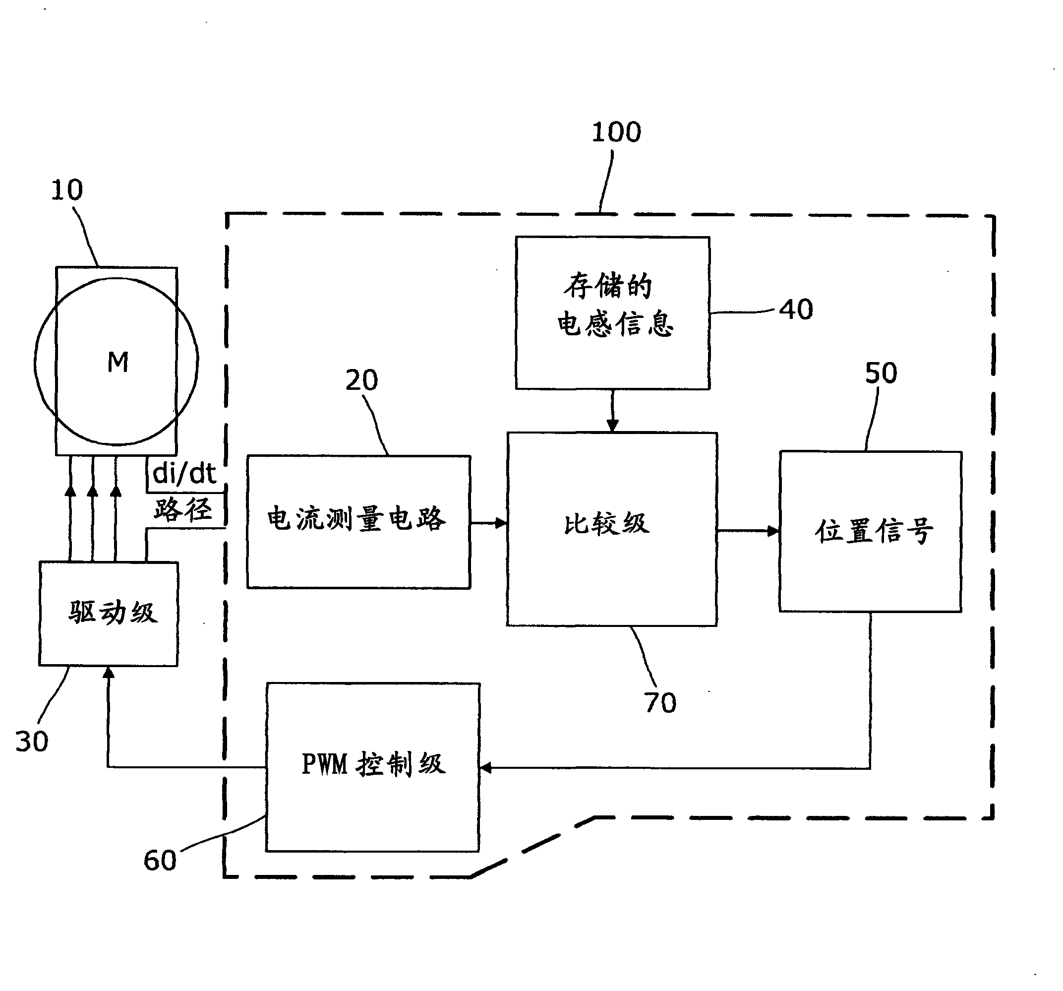
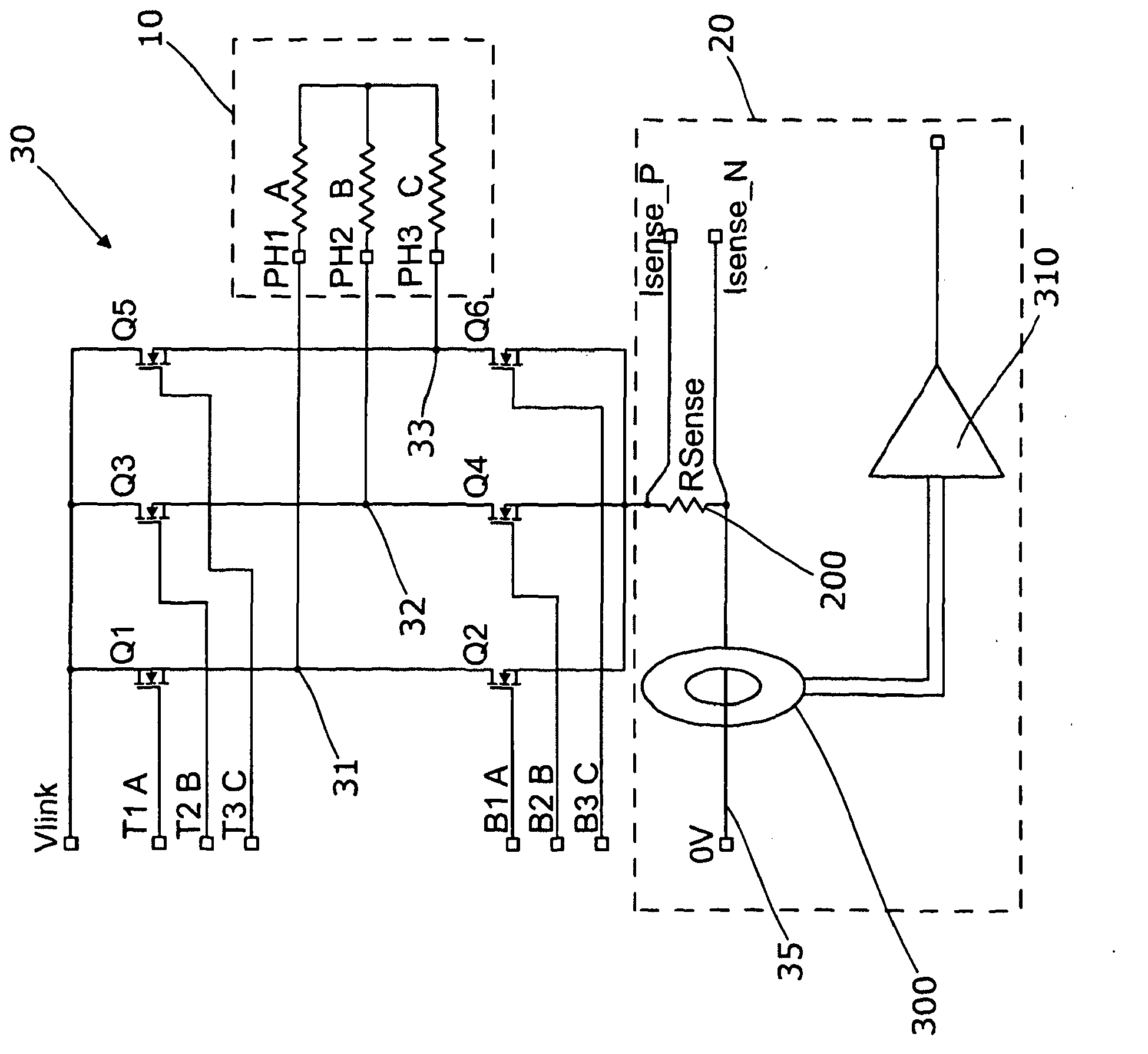
A measurement circuit in a motor circuit generates signals for use in a motor control strategy for an electric motor. The measurement circuit comprises a first current sensing means which produces an output signal indicative of the current flowing in a di / dt path connecting the phases of the motor to a ground or a common positive supply voltage, and further comprises a second current sensing means which produces an output signal indicative of the rate of change of current flowing in the ground line, and in which the second current sensing means comprises a Rogowski coil.

Description

technical field [0001] The invention relates to a measuring device for an electric motor and a drive for an electric motor using the measuring device in determining the angular position of the motor. It has specific applications in electric power steering systems. Background technique [0002] Electric motors have been used in a wide range of situations. One specific area where they have gained application in the last two decades is power steering systems. In such systems, an electric motor is used to provide assist torque to the driver. The electric motor is connected to the steering system and applies a torque that depends on the torque applied to the steering system by the driver. It is generally measured by using a torque sensor attached to the steering column. [0003] In order to control a motor, it is often necessary to know the position of the motor. This measurement can also be used in steering systems to determine the position of the steering stem and thus the...

Claims


Application Information

Patent Timeline
Patent Type & Authority Applications(China)
IPC IPC(8): H02P23/03H02P6/10H02P6/18H02P25/02H02P29/02H02P6/04
CPCH02M7/53875H02P6/10H02P6/186H02P2006/045H02P2203/01H02P2207/05H02P25/03H02P29/0241H02M1/0009H02P6/18H02P25/026
Inventor A·F·麦林M·库达诺斯基
Owner TRW LIMITED
Why Eureka
Eureka Blog
Learn More