Water-saving toilet bowl

A toilet and waterway technology, applied in flushing toilets, water supply devices, indoor sanitary piping devices, etc., can solve the problems of low waste water reuse rate, energy consumption, and inconvenient waste water collection.

Inactive Publication Date: 2013-09-04
李武
View PDF8 Cites 0 Cited by
  • Summary
  • Abstract
  • Description
  • Claims
  • Application Information

AI Technical Summary

Problems solved by technology

The disadvantage of this technical solution is: collecting waste water consumes energy, because the waste water tank is higher than the toilet flushing water tank, which makes waste water collection inconvenient and the waste water reuse rate is low

Method used


Image

  • Water-saving toilet bowl
  • Water-saving toilet bowl
  • Water-saving toilet bowl

Examples


Embodiment 1

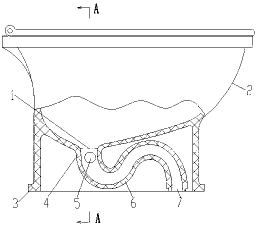
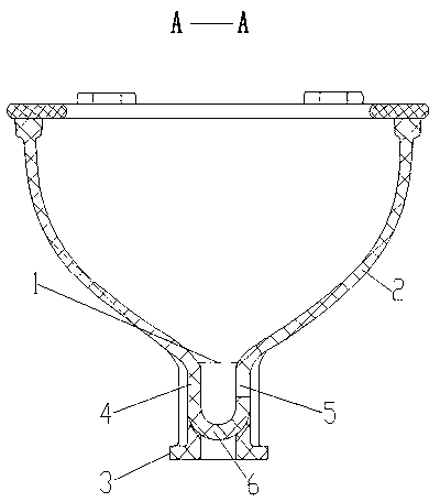
[0017] Embodiment 1: (see figure 1 , figure 2 ) A water-saving toilet, comprising a basin body 2 of the toilet and a drainage pipe 6, the bottom of the basin body 2 communicates with the drainage pipe 6; it is characterized in that: between the upper end surface 1 of the drainage pipe inlet and 200mm below it Water inlet holes 5 are provided on the pipe wall 4 of the discharge pipe between them.

[0018] Usage method: waste water can be discharged into the discharge pipe 6 through the water inlet hole 5 to flush the toilet.

Embodiment 2

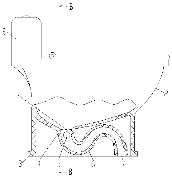
[0019] Embodiment 2: (see image 3 , Figure 4 ) A water-saving toilet, comprising a basin body 2 of the toilet and a drainage pipe 6, the bottom of the basin body 2 communicates with the drainage pipe 6; it is characterized in that: between the upper end surface 1 of the drainage pipe inlet and 200mm below it Water inlet holes 5 are provided on the pipe wall 4 of the discharge pipe between them.

[0020] The preferred structure is: a water inlet hole 5 is provided on the pipe wall 4 of the discharge pipe between the upper end surface 1 of the discharge pipe inlet and 160 mm below it.

[0021] A flushing water tank 8 is provided at the rear of the top of the basin body 2; an annular water channel 9 is provided inside the convex edge of the top of the basin body 2, and a discharge hole 10 facing the inner wall of the basin body 2 is provided at the bottom of the annular water channel 9 , the drain outlet of the flushing water tank 8 communicates with the annular water channel...

Embodiment 3

[0023] Embodiment 3: (see image 3 , Figure 4 ) A water-saving toilet, comprising a basin body 2 of the toilet and a discharge pipe 6, the bottom of the basin body 2 communicates with the discharge pipe 6; its feature is that: between the upper end surface 1 of the discharge pipe inlet and 200mm below it Water inlet holes 5 are provided on the pipe wall 4 of the discharge pipe between them.

[0024] The preferred structure is: a water inlet hole 5 is provided on the pipe wall 4 of the discharge pipe between the upper end surface 1 of the discharge pipe inlet and 160 mm below it. A water inlet hole 5 is provided on the pipe wall 4 of the discharge pipe between the upper end face 1 of the discharge pipe inlet and 120 mm below it.

[0025] A flushing water tank 8 is provided at the rear of the top of the basin body 2; an annular water channel 9 is provided inside the convex edge of the top of the basin body 2, and a discharge hole 10 facing the inner wall of the basin body 2 i...


PUM


Abstract

The invention discloses a water-saving toilet bowl which comprises a basin and a discharge pipeline, wherein the bottom of the basin is communicated with the discharge pipeline. The water-saving toilet bowl is characterized in that a water inlet hole is formed in the wall of the discharge pipeline between the upper end face of an inlet of the discharge pipeline and the lower portion 200mm away from the inlet of the discharge pipeline. Another water inlet hole is formed in the wall of the discharge pipeline between the upper end face of the inlet of the discharge pipeline and the lower portion 160mm away from the inlet of the discharge pipeline, a third water inlet hole is formed in the wall of the discharge pipeline between the upper end face of the inlet of the discharge pipeline and the lower portion 120mm away from the inlet of the discharge pipeline, a flushing tank is arranged in the rear of the top end of the basin, an annular water channel is formed inside a convex edge at the top end of the basin, a discharge hole facing the inner wall of the basin is formed at the bottom of the annular water channel, and a water outlet of the flushing tank is communicated with the annular water channel. Waste water can transversely impact the discharge pipeline of the toilet bowl to flush the toilet bowl at the lowest position, the waste water is conveniently collected and recycled, energy is not consumed, and the toilet bowl is flushed by the flushing tank of the toilet bowl when no waste water is available.

Description

technical field [0001] The invention relates to a water-saving toilet. Background technique [0002] In the prior art, the domestic waste water is reused for flushing the toilet. Most of the washing waste water is pumped into the waste water tank higher than the toilet flushing water tank. The waste water is discharged from the waste water tank into the toilet flushing water tank, and then passes through the toilet bowl. The top protrudes along the internal circular water channel to flush the urinal. The disadvantage of this technical solution is that collecting waste water consumes energy, because the waste water tank is higher than the toilet flushing water tank, which makes waste water collection inconvenient and the waste water reuse rate is low. Long-term use of waste water to flush the toilet will accumulate dirt and breed bacteria on the inner wall of the toilet flushing tank, on the parts of the flushing mechanism, and in the annular water channel in the convex edge...

Claims


Application Information

Patent Timeline
Patent Type & Authority Applications(China)
IPC IPC(8): E03D11/17E03C1/12
Inventor 李武
Owner 李武
Why Eureka
Try Eureka