Check patentability & draft patents in minutes with Patsnap Eureka AI!

Tail-end vibration damper based on rapid energy decay and control method of tail-end vibration damper

A technology of a vibration damping device and a control method, which is applied in the directions of shock absorbers, shock absorbers, springs/shock absorbers, etc., can solve the problems of limited application scope, complicated control schemes, poor low frequency vibration suppression effect, etc. The effect of increasing work efficiency, increasing work speed and range, and reducing control complexity

Inactive Publication Date: 2013-09-04
GUANGDONG UNIV OF TECH
View PDF7 Cites 0 Cited by
  • Summary
  • Abstract
  • Description
  • Claims
  • Application Information

AI Technical Summary

Problems solved by technology

But the above-mentioned high-speed electromagnetic damper has the following deficiencies: 1. The body of the above-mentioned electromagnetic damper is fixed on the high-speed moving actuator, which will increase the quality of the actuator and the influence of motion inertia; 2. The design focus of the above-mentioned electromagnetic damper It is to control the contact damping force, lacking the design of energy absorption and consumption parts, which will lead to a long attenuation time of the residual vibration amplitude of the actuator when it stops; 3. The above-mentioned electromagnetic damper is mainly for high-frequency The vibration suppression effect is not good; 4. The control scheme of the above-mentioned electromagnetic damper is relatively complicated, which limits its application range

Method used


Image

  • Tail-end vibration damper based on rapid energy decay and control method of tail-end vibration damper
  • Tail-end vibration damper based on rapid energy decay and control method of tail-end vibration damper
  • Tail-end vibration damper based on rapid energy decay and control method of tail-end vibration damper

Examples


Embodiment

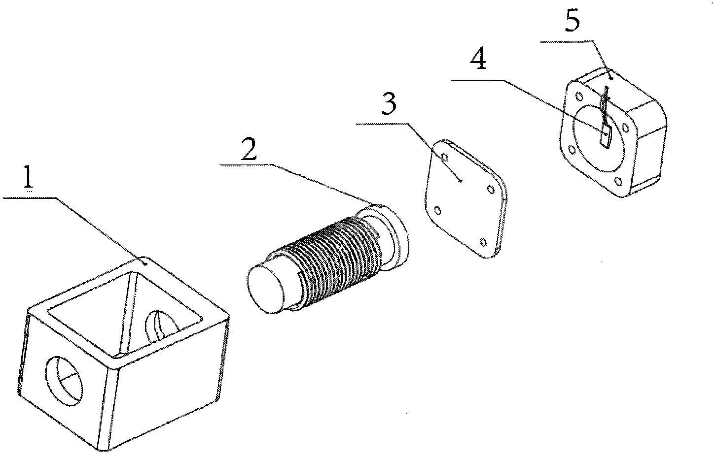
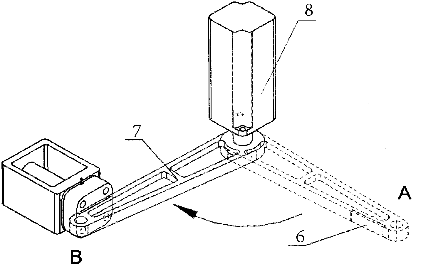
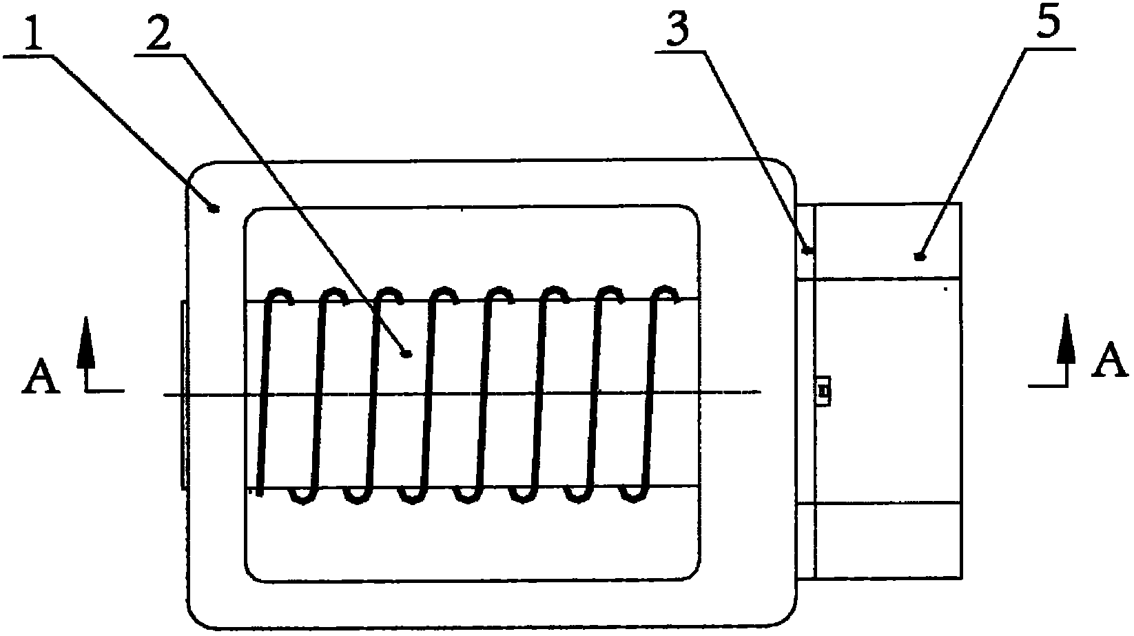
[0027] The structure diagram of the present invention is as figure 1 and figure 2 As shown, the device of the present invention is mainly composed of a housing (1), an electromagnet (2), a support plate (3), a strain gauge (4), an elastic body (5) and an armature (6). Wherein the electromagnet (2) is fixed inside the casing (1), and the support plate (3) and the elastic body (5) are fixed together with the casing (1). Wherein the elastic body (5) has a concave cavity near the electromagnet (2), and the above-mentioned strain gauge (4) is pasted on the middle surface of the concave cavity of the elastic body to directly detect the elastic body Strain, which indirectly detects changes in the pressure an elastomer is subjected to. The armature (6) in the device of the present invention is fixed on the moving part of the main moving device, so that the electromagnetic force of the electromagnet (2) can act on the main moving part.

[0028] Such as figure 2 As shown, the rota...


PUM


Abstract

The invention discloses a tail-end vibration damper based on rapid energy decay and a control method of the tail-end vibration damper which is mainly used for tail-end damping of moving components of microelectronic packaging equipment. The tail-end vibration damper is composed of a body, an armature and a controller. The body is mainly composed of a shell, an electromagnet, a supporting plate, a strain foil, an elastic body and the like. The strain foil is adhered to the middle portion of a recess at the bottom of the elastic body and used for detecting change conditions of strain energy of the elastic body. The electromagnet is mounted inside the shell. The supporting plate and the elastic body are mounted on one side of the shell. The armature is mounted on a moving component of a primary motion device. The elastic body is used for absorbing tail-end residual vibration energy of the primary motion device. The electromagnet is used for consuming energy absorbed by the elastic body. The vibration damping speed of the tail-end vibration damper is high, motion characteristics of a primary motion mechanism are not affected, and working efficiency of the primary motion mechanism can be improved.

Description

technical field [0001] The invention relates to an end vibration damping design of a high-speed light-load motion mechanism, in particular to the field of end vibration damping design of moving parts of microelectronic packaging equipment. Background technique [0002] The moving parts in the microelectronic packaging equipment need to go back and forth frequently to and from different stations to perform different operations during the working process. In order to improve the production efficiency of the above-mentioned equipment, the moving parts of the above-mentioned equipment need to have the characteristics of high moving speed and fast and stable stop. In microelectronic packaging equipment, in order to reduce the influence of motion inertia, its high-speed moving working parts often adopt lightweight design, and the above-mentioned working parts are mostly rod-shaped parts with a certain length, and their damping ratio is very small. Due to the influence of the moti...

Claims


Application Information

Patent Timeline
Patent Type & Authority Applications(China)
IPC IPC(8): F16F7/00
Inventor 杨志军白有盾陈新高健刘冠峰陈新度杨海东王梦
Owner GUANGDONG UNIV OF TECH
Features
  • R&D
  • Intellectual Property
  • Life Sciences
  • Materials
  • Tech Scout
  • Unparalleled Data Quality
  • Higher Quality Content
  • 60% Fewer Hallucinations
Learn More