High-enthalpy wind bathing device

A technology with high enthalpy and air ducts, applied in ventilation systems, space heating and ventilation, space heating and ventilation details, etc. The effect of increasing temperature and humidity, oxygen partial pressure, and improving the uniformity of the temperature and humidity field in the bathroom

Active Publication Date: 2013-09-04
浙江鼎美智装股份有限公司
View PDF6 Cites 10 Cited by
  • Summary
  • Abstract
  • Description
  • Claims
  • Application Information

AI Technical Summary

Problems solved by technology

[0020] The purpose of the present invention is to provide a high-enthalpy bathing wind to solve the problem of low temperature and humidity at the bottom of the bathroom in the wint

Method used


Image

  • High-enthalpy wind bathing device
  • High-enthalpy wind bathing device
  • High-enthalpy wind bathing device

Examples


Embodiment 1

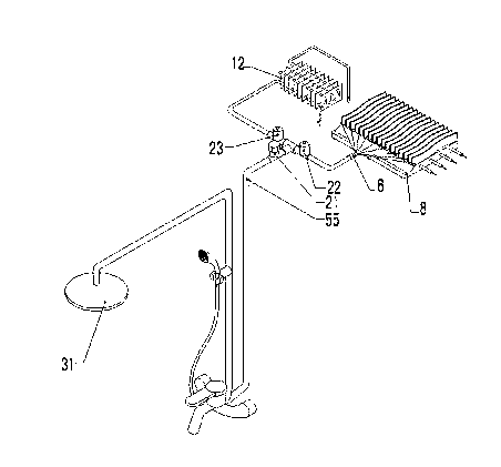
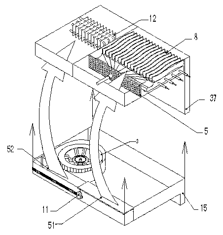
[0043] see Figure 1 to Figure 7 , a high enthalpy air bath, comprising a high air enthalpy subsystem 2, an air duct switching device 11 and a cooling, dehumidifying and oxygenating subsystem 1, wherein:

[0044] The high air enthalpy subsystem 2 can adopt the subsystem disclosed in the application number 201110255087.3, and switch between the high air enthalpy subsystem and the cooling, dehumidification and oxygenation subsystem 1 through the air duct switching device 11 .

[0045] For example, the high air enthalpy subsystem 2 at least includes an accommodating space for heat generation and heat transfer formed in the heat-insulating shell. An air suction port and an air exhaust port can be respectively set on the accommodating space. Starting from the air suction port, centrifugal Fan, wind bag, equalizer plate 5, fan nozzle 6, transition cavity, finned electric heating plate group 8, exhaust pipe, until the air outlet. The air bag, the equalizing plate 5, the fan nozzle 6...

no. 2 example

[0104] The present invention may also only include the cooling, dehumidification and oxygenation subsystem.

[0105] A high-enthalpy wind bath, including cooling, dehumidification and oxygenation subsystems, wherein:

[0106] The cooling, dehumidification and oxygenation subsystem further includes a tube-fin heat exchanger arranged in the air suction port, a centrifugal fan, and an air duct. One side of the tube-fin heat exchanger is connected to a tap water pipeline, and the tube-fin heat exchanger The fin side of the finned heat exchanger communicates with the air outlet of the centrifugal fan. When bathing at high temperature in summer or with high air enthalpy in winter, the subsystem can be activated. At this time, low-temperature tap water flows through the tube-fin heat exchanger. On the inner side of the tube, the indoor high-temperature and high-humidity air pressed by the centrifugal fan flows through the fin side of the tube-fin heat exchanger, and the hot and humid...


PUM


Abstract

The invention discloses a high-enthalpy wind bathing device which comprises a high-air-enthalpy subsystem, a cooling dehumidification oxygenation subsystem and an air flue switching device. The high-air-enthalpy subsystem is used for carrying out temperature rising and humidification on air in a toilet, absorbing air at the high position in the toilet and discharging air at the low position in the toilet, or absorbing air at the low position in the toilet and discharging air at the high position in the toilet, and forming vertical warm and wet airflow surrounding a bather so as to achieve the effects of rising temperature and humidity at the bottom of the toilet and improving homogeneity of a temperature field and a humidity field in the toilet. The cooling dehumidification oxygenation subsystem is characterized in that low-temperature tap water flows through tubes of a finned tube heat exchanger, heat exchange is carried out on the water and the toilet high-temperature high-humidity air which is pressed in the toilet by a centrifugal fan and flows through fins of the finned tube heat exchanger so as to achieve cooling and dehumidification, the temperature of air is reduced, partial pressure of water vapor is reduced, air outside the toilet is attracted into the toilet for supplement, therefore, air density in the toilet is increased, partition pressure of oxygen is increased, oxygenation is achieved, and therefore the phenomenon of dizziness, caused by oxygen deficits, of the bather can be effectively prevented.

Description

technical field [0001] The present invention relates to an indoor heating and humidifying device, in particular to a high-level device for improving the thermal comfort and safety of bathing in the bathroom with low-level suction and high-level air outlet (or high-level suction and low-level air output) and the function of cooling, dehumidification and oxygenation. Enthalpy Mufeng. Background technique [0002] The bathroom has become the most important unit space in real family life, where family members wash, bathe and go to the toilet to complete the key links in family and personal hygiene activities. But there are following problems in actual family toilet and winter bath: [0003] 1. The power distribution capacity of the bathroom is small [0004] In residential design, bathroom power distribution mainly considers the power demand of Yuba, washing machine, and lighting. The cross-sectional area of ​​wires such as copper core wires is usually 2.5mm 2 , The rated loa...

Claims


Application Information

Patent Timeline
IPC IPC(8): F24F7/08F24F9/00F24F13/30
Inventor 薛世山李成伟韦林林姜城马骥陈红荣周孑民周萍薛世明薛世东
Owner 浙江鼎美智装股份有限公司
Why Eureka
Try Eureka