
Displacement adjusting device

A technology of displacement adjustment and micro-displacement, which is applied in installation, optics, instruments, etc., can solve problems such as application limitations, achieve the effects of improving accuracy and performance, facilitating adjustment, and avoiding adjustment errors

Active Publication Date: 2013-09-04
TSINGHUA UNIV
View PDF4 Cites 2 Cited by
  • Summary
  • Abstract
  • Description
  • Claims
  • Application Information

AI Technical Summary

Problems solved by technology

When the actuation direction is parallel to the mirror surface, the actuator acts on the edge of the mirror and can only be used to correct specific aberrations such as defocus and astigmatism, so the application in adaptive optics systems is limited.

Method used


Image

  • Displacement adjusting device
  • Displacement adjusting device
  • Displacement adjusting device

Examples


Embodiment Construction

[0026] Embodiments of the present invention are described in detail below, examples of which are shown in the drawings, wherein the same or similar reference numerals designate the same or similar elements or elements having the same or similar functions throughout. The embodiments described below by referring to the figures are exemplary and are intended to explain the present invention and should not be construed as limiting the present invention.

[0027] In describing the present invention, it should be understood that the terms "center", "longitudinal", "transverse", "length", "width", "thickness", "upper", "lower", "front", " Orientation or position indicated by "back", "left", "right", "vertical", "horizontal", "top", "bottom", "inner", "outer", "clockwise", "counterclockwise", etc. The relationship is based on the orientation or positional relationship shown in the drawings, and is only for the convenience of describing the present invention and simplifying the descrip...


PUM


Abstract

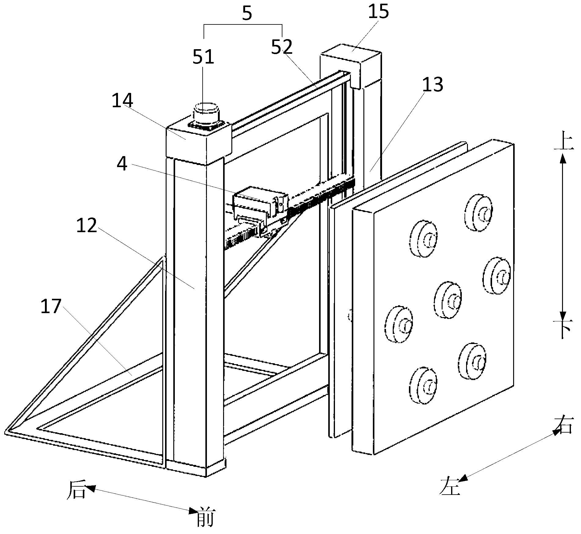
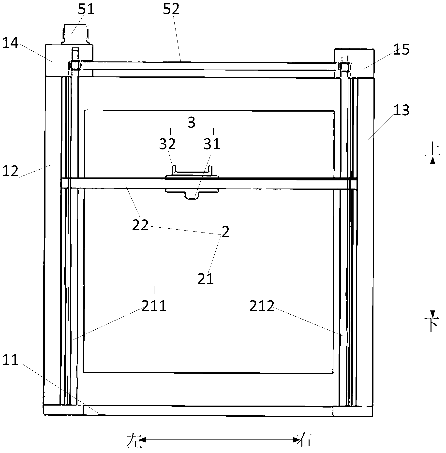
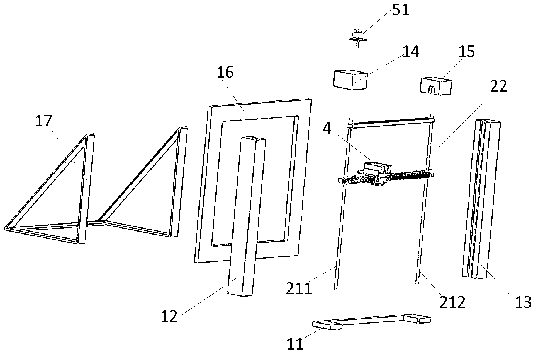
The invention discloses a displacement adjusting device which comprises a support, a guiding component, a micro-adjusting component, a micro-displacement meter and a driving component. Specifically, the guiding component is arranged on the support, the micro-adjusting component is arranged on the guiding component in a movable mode in a first straight line direction and a second straight line direction, the micro-displacement meter is movably arranged on the micro-adjusting component in a movable mode in a third straight line direction, wherein the first straight line direction, the second straight line direction and the third straight line direction are perpendicular to one another, the driving component is used for driving the micro-adjusting component to move, and the micro-adjusting component is respectively connected with the guiding component and the micro-adjusting component. The displacement adjusting device can be used for detecting the micro displacement of each actuating point of a deforming mirror quickly, efficiently and accurately, and accordingly high stress adjusting accuracy is achieved.

Description

technical field [0001] The invention relates to the field of adaptive optical systems, in particular to a displacement adjustment device. Background technique [0002] Deformable mirrors, also known as deformable mirrors, are mainly used in various adaptive optics systems. As a wavefront correction device to correct wavefront errors, they play an extremely important role in adaptive optics systems. One of the important components, the research and development of the deformable mirror is related to the correction ability and correction accuracy of the whole adaptive optics system. [0003] The deformable mirror compensates the wavefront phase distortion by changing its surface shape, which can be divided into two types: continuous surface shape and discrete surface. The advantage of continuous surface deformation mirror is that it can obtain continuous surface shape and high correction accuracy. The disadvantage is that the deformation of the surface shape is relatively smal...

Claims


Application Information

Patent Timeline
IPC IPC(8): G02B7/185
Inventor 黄磊巩马理闫平薛峤李腾浩柳强冯泽心康少男孙冶闫海波
Owner TSINGHUA UNIV
Learn More