
Smart card identification system applied in identification field and method for reading and modifying the same

A smart card and smart card technology, applied in the field of smart identification, to achieve the effects of low production cost, reliable connection relationship, good security and confidentiality

Active Publication Date: 2016-02-10
HANRUN ELECTRONICS
View PDF4 Cites 0 Cited by
  • Summary
  • Abstract
  • Description
  • Claims
  • Application Information

AI Technical Summary

Problems solved by technology

[0002] In the process of daily life, production, and equipment maintenance, various objects need to be marked. Traditionally, flat printing is used for marking, such as sticking notes, adding labels, etc. With the advancement of technology, there are The label reading method of barcode and two-dimensional code is introduced. The main principle is to convert the identification information into barcode and two-dimensional code and print it on the object or label, and then read the barcode and two-dimensional code by infrared or taking pictures. Information, decode it to restore the identification information, but the amount of information stored in barcodes and two-dimensional codes is small, the security and confidentiality are poor, and the information cannot be read easily due to damage or dirt on the surface, and when the information needs to be replaced Sometimes need to re-label, can not be reused
[0003] At present, radio frequency identification technology is also used for identification. The main principle is to read or modify the information in the radio frequency identification card through wireless RFID signals. This method has a long reading distance, large data that can be stored, and the data content can be modified. The current radio frequency identification card needs to have a built-in antenna, so it is bulky and inconvenient to use in a small and dense environment. When the radio frequency identification card is placed relatively densely, it will interfere with each other during identification, and then it cannot be used. Because it is transmitted through wireless signals, its confidentiality and security are poor, and the cost is high and it is not easy to promote
[0004] Especially in the existing telephones, network switches and optical fiber adapters, in order to facilitate the staff to identify the users of each line, the existing practice is to bind each cable or optical fiber with a label for recording personal information, and the staff pass Find the label to find the cable used by the corresponding customer, but this will bring a lot of inconvenience in the process of use, for example: if the user's information is changed, a new label needs to be made for replacement, not only the production time is long but also It is easy to make mistakes, and because the cables or optical fiber lines are densely distributed, the labels are generally small, which is inconvenient for the staff to find, and only the basic information of customers can be recorded, which is very inconvenient for management
With the application of smart cards, especially smart SIM cards, more and more widely, its size is getting smaller and larger, and it is safe and reliable. It is very suitable for storing identification data, but because traditional smart cards need to be manually inserted into the card reader The relevant information can only be read in the slot of the card, and the operation is very troublesome. At present, there is a lack of an efficient smart card identification system

Method used


Image

  • Smart card identification system applied in identification field and method for reading and modifying the same
  • Smart card identification system applied in identification field and method for reading and modifying the same
  • Smart card identification system applied in identification field and method for reading and modifying the same

Examples


Embodiment approach

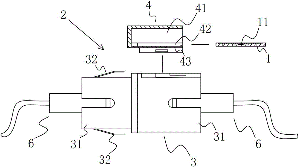
[0069] refer to Figure 8 As shown, it is the second embodiment of the smart card mounting base 2 of the present invention, the installation body 3 is a network adapter distribution frame installed with a plurality of network adapters, and the smart card accommodating part 4 is arranged on the network adapter distribution frame On the side of the smart card accommodating part 4 is provided with a smart card slot 42 for placing the contact smart card 1, and the smart card slot 42 is provided with an opening that at least exposes the entire metal contact part 11 of the contact smart card 1 , the smart card slot 42 communicates with the smart card reading interface 41 through an opening. Due to the large storage capacity of the contact smart card 1, the user information of the entire network adapter distribution frame can be saved. By setting the smart card accommodating part 4 installed with the contact smart card 1 on the side of the network adapter distribution frame, the card...


PUM


Abstract

The invention discloses an intelligent card marking system in the marking field as well as a reading and modifying method thereof. The intelligent card marking system comprises an intelligent card installation base with a contact intelligent card, wherein the intelligent card installation base comprises an installation body and an intelligent card storage part which is arranged on the installation body, the contact intelligent card is arranged in the intelligent card storage part, and the intelligent card storage part is provided with an intelligent card reading interface which is used for inserting an intelligent card reading strip and an intelligent card reader for reading the marking information of the contact intelligent card. The contact intelligent card is used for marking an object, not only is the storage capacity large, the size small and the use convenient under the intensive and miniaturized situation, but also when the information is altered, the information in the contact intelligent card can be modified in time, the intelligent card is unnecessary to reproduce, the production cost is low, the intelligent card marking system is easy to popularize, by adopting the contact connecting way, the connection relation is reliable, the interference can be avoided, and the safety and the confidentiality are good.

Description

technical field [0001] The invention relates to the field of smart identification, in particular to a smart card identification system and its reading and modifying methods applied in the field. Background technique [0002] In the process of daily life, production, and equipment maintenance, various objects need to be marked. Traditionally, flat printing is used for marking, such as sticking notes, adding labels, etc. With the advancement of technology, there are The label reading method of barcode and two-dimensional code is introduced. The main principle is to convert the identification information into barcode and two-dimensional code and print it on the object or label, and then read the barcode and two-dimensional code by infrared or taking pictures. Information, decode it to restore the identification information, but the amount of information stored in barcodes and two-dimensional codes is small, the security and confidentiality are poor, and the information cannot b...

Claims


Application Information

Patent Timeline
Patent Type & Authority Patents(China)
IPC IPC(8): G06K7/00
Inventor 陈泽平刘红斌
Owner HANRUN ELECTRONICS
Learn More