Magnetic tunnel junction device with separate read and write paths

A magnetic and data reading technology, which is used in the manufacture/processing of electromagnetic devices, magnetic field-controlled resistors, digital memory information, etc. The effect of current reduction

Active Publication Date: 2013-09-04
QUALCOMM INC
View PDF5 Cites 5 Cited by
  • Summary
  • Abstract
  • Description
  • Claims
  • Application Information

AI Technical Summary

Problems solved by technology

However, the dual MTJ design sets a further limit on the MTJ resistance and a greater sensitivity to the data read sensing margin

Method used


Image

  • Magnetic tunnel junction device with separate read and write paths
  • Magnetic tunnel junction device with separate read and write paths
  • Magnetic tunnel junction device with separate read and write paths

Examples


Embodiment Construction

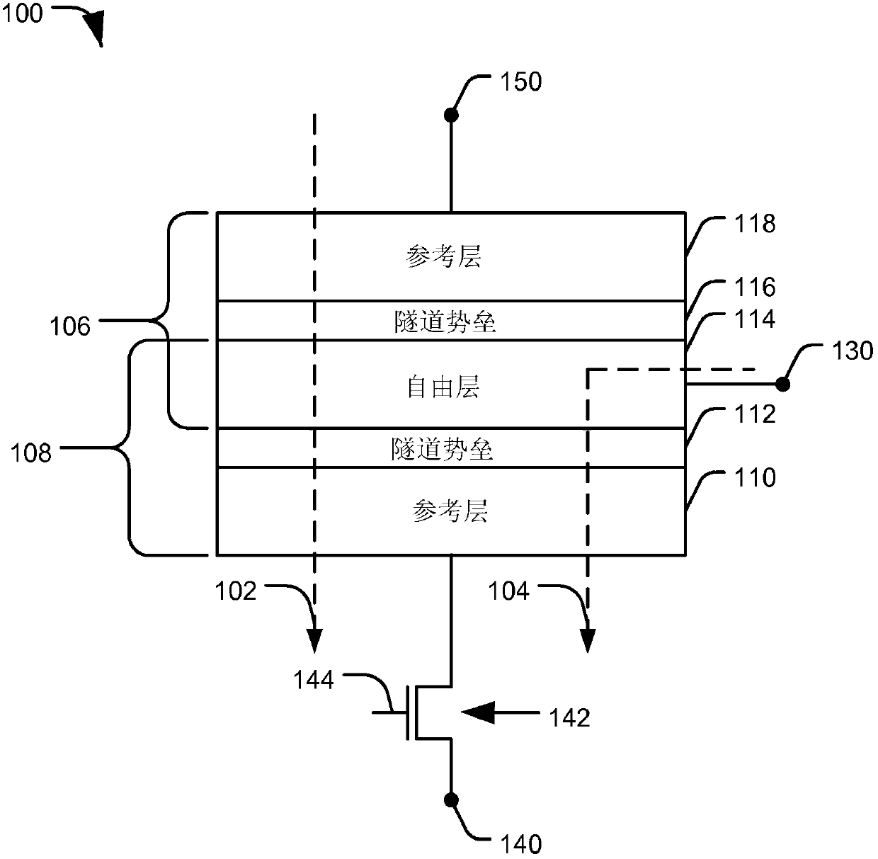
[0030] see figure 1 , a diagram depicting a particular illustrative embodiment of a magnetic tunnel junction (MTJ) device having separate data read and write paths, and generally designated 100 . In a particular embodiment, device 100 may be included in an STT-MRAM bit cell. Data read path 102 and data write path 104 provide separate current paths coupled to the MTJ structure of device 100 . The first reference layer 110 , the tunnel barrier layer 112 and the free layer 114 form the first MTJ component 108 . The free layer 114 , the second tunnel barrier layer 116 and the second reference layer 118 form the second MTJ assembly 106 . Write terminal 130 is coupled to free layer 114 . The read terminal 150 is coupled to the second reference layer 118 . A switch 142 , such as a transistor, is coupled between the first reference layer 110 and the source terminal 140 . A switch 142 is coupled to receive a control signal 144 . In a particular embodiment, device 100 may be part...


PUM


Abstract

In an embodiment, a device is disclosed that includes a magnetic tunnel junction (MTJ) structure. The device also includes a read path (102) coupled to the MTJ structure and a write path (104) coupled to the MTJ structure. The write path (104) is separate from the read path (102). The device in substance comprises a pair of serially coupled MTJ structures (106, 108), whereby the read path (102) comprises only one of the MTJ structure (108). This provides for combined improved read margin and improved write margin.

Description

[0001] Divisional statement [0002] This case is the patent application titled "Magnetic Tunnel Junction Device with Separate Read and Write Paths", the priority date is December 19, 2007, the application number is 200880125501.5, and the application date is December 19, 2008 Divisional application. technical field [0003] The present invention is generally directed to a device including a magnetic tunnel junction (MTJ) structure with separate read and write data paths. Background technique [0004] Conventional spin-transfer torque magnetic random access memory (STT-MRAM) bitcells contain transistors and magnetic tunnel junction (MTJ) structures. The basic MTJ structure consists of two magnetic electrodes sandwiching an oxide tunnel barrier layer. The magnetic moment of each magnetic electrode is oriented along the long axis of the transversely elongated member. The parallel and antiparallel magnetic moment orientations between the two magnetic layers on either side o...

Claims


Application Information

Patent Timeline
Patent Type & Authority Applications(China)
IPC IPC(8): G11C11/16
CPCY10S977/933Y10S977/935G11C11/1655G11C11/1659G11C11/161G11C11/1673G11C11/1675G11C11/16H10N50/01H10N50/10
Inventor 朱晓春顾时群李霞升·H·康
Owner QUALCOMM INC
Why Eureka
Try Eureka