Dual in-line package (DIP) LED (Light Emitting Diode) automatic forming device capable of positioning height and DIP LED automatic forming method

An automatic molding and in-line technology, applied in the electronic field, can solve the problems of LED body resin cracking, special materials, not suitable for multi-model and small batch production, etc., and achieve the effect of convenient mechanical automatic bonding and pressing

Inactive Publication Date: 2013-09-04
东莞龙迈智能电子科技有限公司
View PDF5 Cites 1 Cited by
  • Summary
  • Abstract
  • Description
  • Claims
  • Application Information

AI Technical Summary

Problems solved by technology

[0002] LEDs are widely used in electronic industries such as household appliances, automobiles, aerospace, consumer goods, medical care, industrial automation equipment and instruments. All kinds of in-line LEDs used in the industry are placed on the pins of the LED according to the height requirements of the product structure. Add a suitable LED bracket by manual operation and then insert it into the pad hole of the PCB by manual operation. With the increase of labor costs and the popularization of automatic plug-in equipment, manual operation has restricted the production efficiency and product quality of electronic circuit boards. quality
[0003] The existing automatic plug-in equipment can complete the action of directly inserting the in-line LED into the pad hole of the PCB, but because there is no height positioning piece on the pin of the in-line LED, the automatic plug-in equipment can only insert The in-line LED is inserted to the bottom, that is, to the position where the resin bottom of the in-line LED is close to the PCB board; if the in-line LED is inserted to the end, the following problems will occur: First, the in-line LED with a diameter of less than 5mm is due to The reason for the packaging resin is that the package is easy to be strained, causing quality hazards; the second is that it is easy to damage the in-line LED due to high temperature when soldering with a wave soldering furnace, especially when using lead-free solder (generally, the soldering temperature of the soldering furnace is 260°C± 5°C); the third is that it cannot meet the requirements of the product structure height, but the design height of the panel-mounted PCBA part of the whole machine must be determined by the package height of the in-line LED, which increases the requirements for product shell design
[0004] At present, the industry usually samples the following two methods to achieve the purpose of automatically inserting the in-line LED into the pad hole of the PCB according to the height requirements of the product structure through automatic plug-in equipment. One is to use the pins of the in-line LED Determine the required "K" point (commonly known as: frog legs) and then insert it into the pad hole of the PCB with an automatic plug-in device. This positioning method has certain application limitations, which is reflected in: the height of the pins at the bottom of the LED It must be greater than or equal to 3mm, otherwise the equipment stress at the "K" point will easily tear the LED body resin and cause quality problems; when the height of the bottom pins of the LED is greater than or equal to 6mm, when using automatic plug-in equipment, the automatic plug-in equipment generally uses claws to grasp Hold the component pins, and then use the lighting equipment to calibrate the pad holes of the PCB board, apply stress from the top of the component to drive the component pins into the pad holes of the PCB board, and the LED pins and the PCB board only rely on the "K" point on both sides At this time, the resin weight of the LED body and the stress exerted by the automatic plug-in equipment will easily cause the LED light-emitting point to deviate, affecting the installation and visual effect of the PCBA
The second is to use different packaging heights for in-line LEDs according to the height requirements of the product structure. The disadvantages of this method are: special materials, high LED production costs; difficult procurement and storage, not suitable for small batch production of multiple models

Method used


Image

  • Dual in-line package (DIP) LED (Light Emitting Diode) automatic forming device capable of positioning height and DIP LED automatic forming method
  • Dual in-line package (DIP) LED (Light Emitting Diode) automatic forming device capable of positioning height and DIP LED automatic forming method
  • Dual in-line package (DIP) LED (Light Emitting Diode) automatic forming device capable of positioning height and DIP LED automatic forming method

Examples


Embodiment Construction

[0030] The specific embodiments of the present invention will be further described below in conjunction with the accompanying drawings.

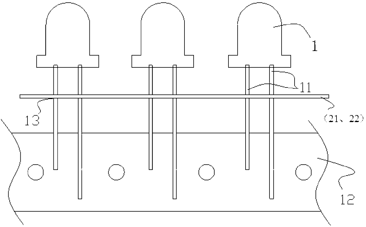
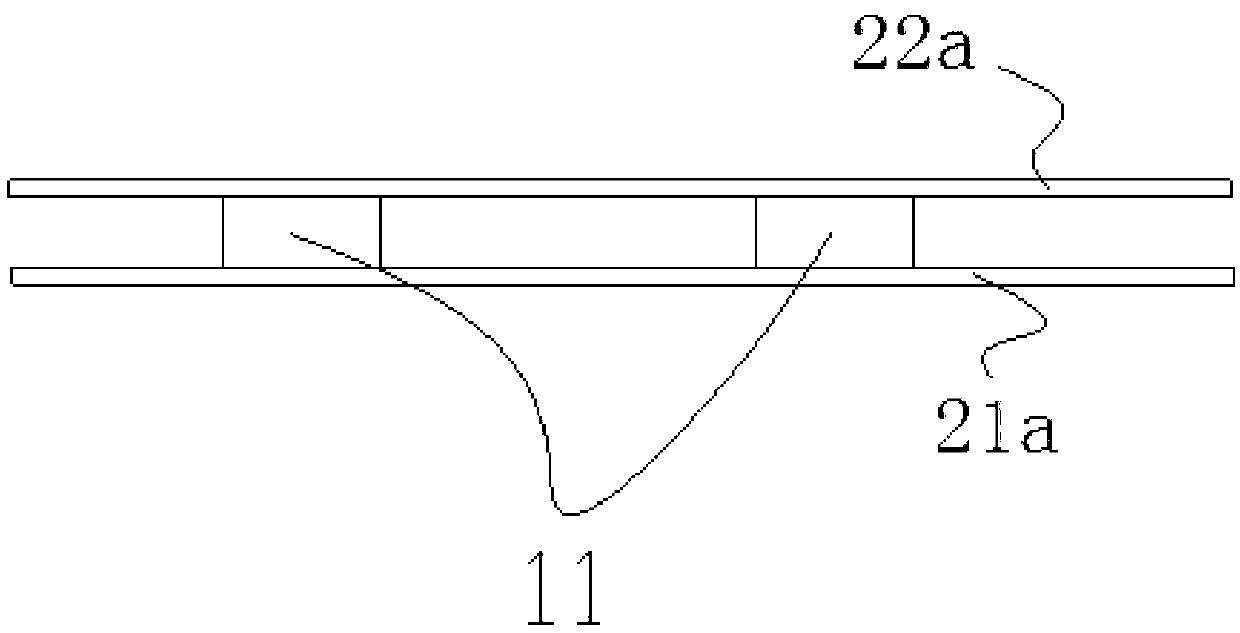
[0031] Such as figure 1 and 2 As shown, the in-line LED of the present invention includes an in-line LED body 1 and insulating height positioning adhesive strips bonded to two pins 11 of the in-line LED body 1, and the bottom surfaces of all height positioning adhesive strips are plane, and the bottom surfaces of all height positioning strips are on the same horizontal plane 13 perpendicular to the pins. Here, the connection position of the highly positioned rubber strip only needs to enable the in-line LED body to be supported on the PCB under the action of the automatic plug-in device. In this embodiment, the cross section of the height positioning rubber strip is square.

[0032] In order to simplify the molding process, such as figure 2 The shown embodiment adopts two height positioning strips 21a, 22a, the height positioning strip ...


PUM


Abstract

The invention discloses a dual in-line package (DIP) LED (Light Emitting Diode) automatic forming device capable of positioning height and a DIP LED automatic forming method. The device comprises DIP LED bodies and height positioning rubber bars which are fixedly connected to two pins of each DIP LED body, wherein the bottom surfaces of all the height positioning rubber bars are planes and are located on the same plane vertical to the pins; the method comprises the steps of applying bonding force on the DIP LED bodies on opposite braids of the upper and lower height positioning rubber bars; reliably bonding the upper and lower height positioning rubber bars on the front faces and back faces of all the DIP LED bodies on the braids; and finally punching the positions of the upper and lower height positioning rubber bars between two adjacent DIP LED bodies on the braids to form each DIP LED capable of positioning height. Automatic plugging can be completed through an automatic plug-in device in the way that the height positioning rubber bars on the pins of the DIP LED bodies, an original braiding mode is not needed to be changed, and no influence is caused on the element performance.

Description

technical field [0001] The invention belongs to the field of electronic technology, and in particular relates to an automatic forming device and an automatic forming method of a height-positioned in-line (DIP) LED that can be directly inserted into a pad hole of a PCB board at a predetermined height through an automatic plug-in device. Background technique [0002] LEDs are widely used in electronic industries such as household appliances, automobiles, aerospace, consumer goods, medical care, industrial automation equipment and instruments. All kinds of in-line LEDs used in the industry are placed on the pins of the LED according to the height requirements of the product structure. Add a suitable LED bracket by manual operation and then insert it into the pad hole of the PCB by manual operation. With the increase of labor costs and the popularization of automatic plug-in equipment, manual operation has restricted the production efficiency and product quality of electronic cir...

Claims


Application Information

Patent Timeline
Patent Type & Authority Applications(China)
IPC IPC(8): H01L33/48
Inventor 夏运明吴群生吴勇坤贺白云莫经海
Owner 东莞龙迈智能电子科技有限公司
Why Eureka
Try Eureka