Supercharge Your Innovation With Domain-Expert AI Agents!

Method for temporarily wiring 35kV medium voltage cables for narrow space

A temporary wiring, narrow ground technology, applied in the direction of connecting/terminating cables, etc., can solve the problems of narrow space, difficult wiring of high-voltage terminals, damaged cable ends, etc.

Active Publication Date: 2013-09-04
STATE GRID CORP OF CHINA +1
View PDF3 Cites 2 Cited by
  • Summary
  • Abstract
  • Description
  • Claims
  • Application Information

AI Technical Summary

Problems solved by technology

[0003] In order to solve the problem that the terminal of the high-voltage line is difficult to connect due to the narrow space in the transformer well, and the original cable end will be damaged, the present invention proposes a temporary connection method for 35kV medium-voltage cables in a narrow place

Method used


Image

  • Method for temporarily wiring 35kV medium voltage cables for narrow space
  • Method for temporarily wiring 35kV medium voltage cables for narrow space
  • Method for temporarily wiring 35kV medium voltage cables for narrow space

Examples


specific Embodiment approach 1

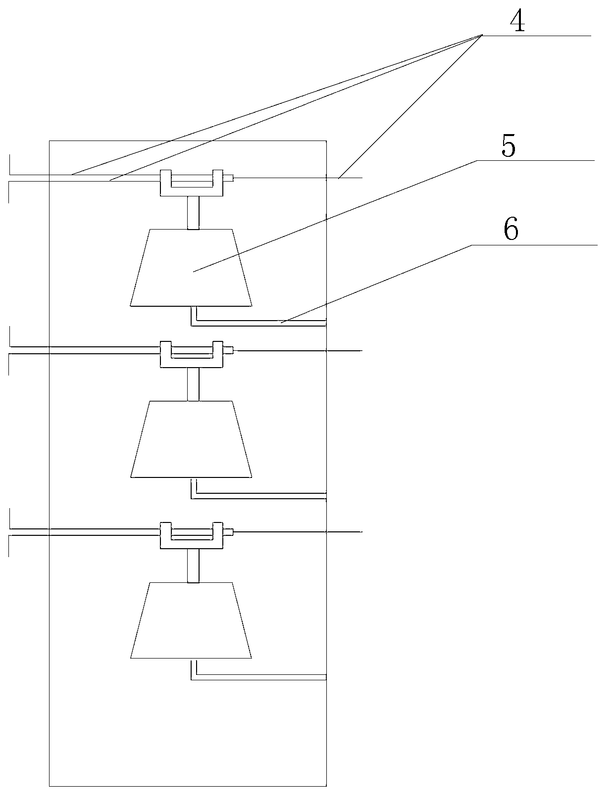
[0018] Specific implementation mode one: see figure 1 , figure 2 and Figure 4 Describe this embodiment, a temporary connection method for 35kV medium-voltage cables used in narrow places described in this embodiment. Steel frame 6, three insulators 5 are arranged on the supporting steel frame 6, the temporary wiring method of each phase cable is the same, and the wiring method of one phase cable is:

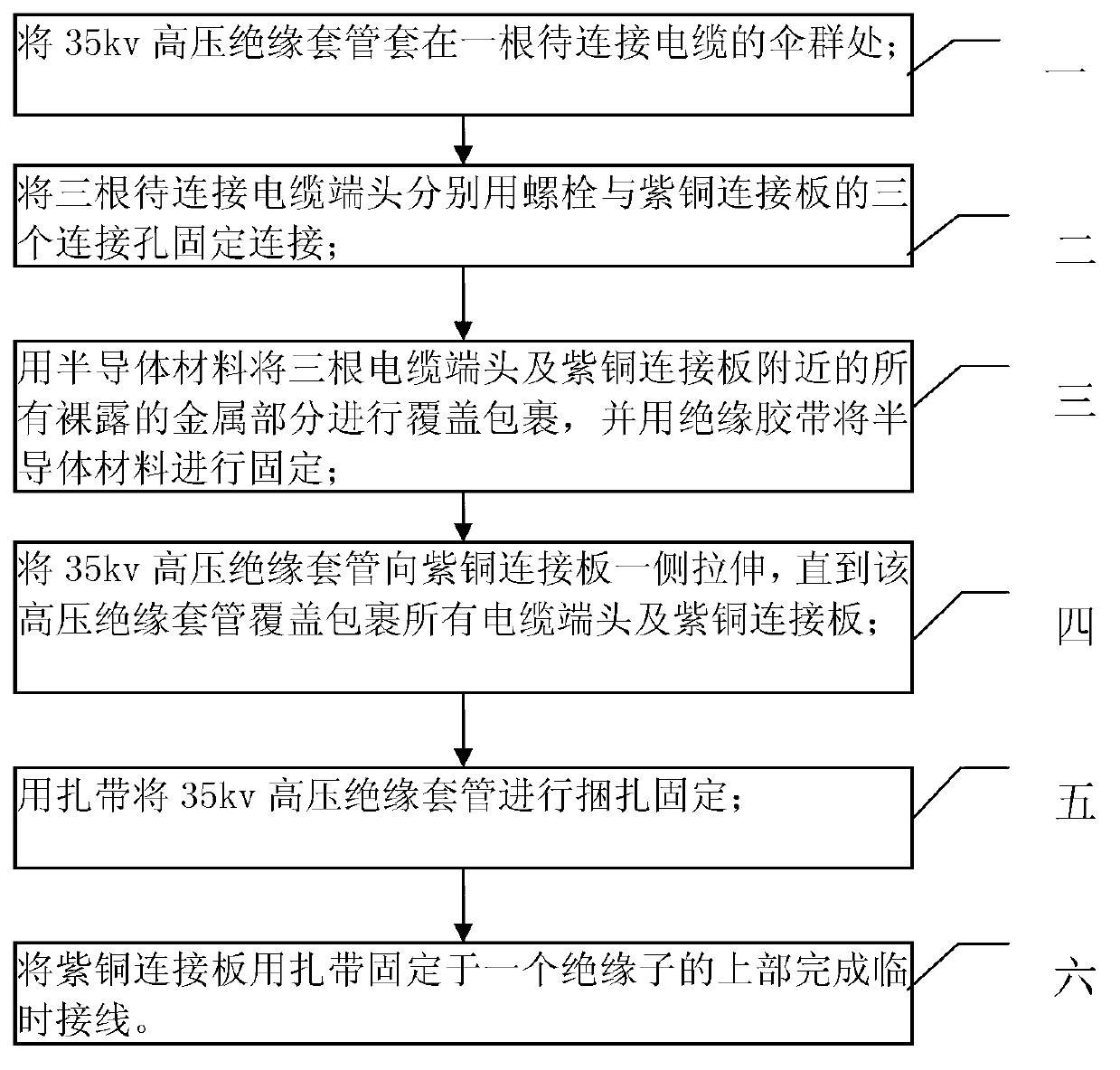
[0019] Step 1: Put the 35kv high-voltage insulating sleeve 1 on an umbrella group of cables to be connected;

[0020] Step 2: Fix and connect the three cable ends 4 to be connected to the three connection holes of the copper connecting plate 3 with bolts;

[0021] Step 3: Cover and wrap all the exposed metal parts near the three cable ends 4 and the copper connecting plate 3 with the semiconductor material 2, and fix the semiconductor material 2 with insulating tape;

[0022] Step 4: Stretch the 35kv high-voltage insulating sleeve 1 toward the copper connecting plate 3 unti...

specific Embodiment approach 2

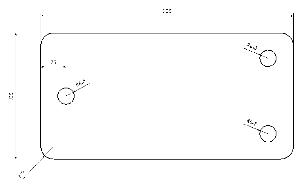
[0028] Specific embodiment 2: This embodiment is a further limitation of the temporary wiring method for 35kV medium voltage cables in narrow places described in specific embodiment 1. The copper connecting plate 3 in the step 2 is 180mm to 100mm long. 210mm, a copper plate with a width of 80mm to 110mm and a thickness of 6mm to 9mm.

specific Embodiment approach 3

[0029] Specific implementation mode three: see image 3 Describe this embodiment, this embodiment is a further limitation of a temporary connection method for 35kV medium-voltage cables in a narrow place described in the second embodiment, the copper connecting plate 3 in the second step is 200mm long, A copper plate with a width of 100mm and a thickness of 8mm.


PUM

PropertyMeasurementUnit
Thicknessaaaaaaaaaa
Thicknessaaaaaaaaaa
Radiusaaaaaaaaaa

Abstract

The invention relates to a method for temporarily wiring 35kV medium voltage cables for a narrow space, belonging to the technical field of medium and high voltage wiring. The method solves the problems that high voltage cable terminals are difficult to wire and the original cable termination points can be damaged because of the narrow space inside a transformer well. The method comprises the following steps: sleeving a 35kV high voltage insulating sleeve at an umbrella group of a cable to be connected; fixedly connecting the termination points of three cables to be connected by using three connecting holes of bolts and a red copper connecting plate respectively; covering and wrapping the termination points of the three cables and all exposed metal parts close to the red copper connecting plate by using a semiconductor material, and fixing the semiconductor material by using an insulating tape; drawing the 35kV high voltage insulating sleeve towards one side of the red copper connecting plate till all the termination points and the red copper connecting plate are covered and wrapped; binding and fixing the high voltage insulating sleeve by using a ribbon; and fixing the red copper connecting plate at the upper parts of insulators by using ribbons so as to complete temporary wiring. The method is suitable for temporarily wiring the medium voltage cables in a narrow and damp space.

Description

technical field [0001] The invention belongs to the technical field of medium and high voltage wiring, and in particular relates to the temporary connection of medium voltage cables that need to be connected at a voltage level of 35kV or below in a narrow humid space. Background technique [0002] The space in the transformer well is narrow, and due to the rainy season, there is a thin layer of water on the ground in the well, and the humidity in the well is very high. At the same time, the owner put forward another harsh condition. After the test, the original wiring should be restored and the original cables should not be damaged, which brought challenges to the wiring method. In a humid environment, when the distance between the 35kV line terminals is only 20cm at most, it is impossible to complete the interconnection of three high-voltage cable ends without damaging the original cable ends, which is impossible in the past traditional wiring methods. In most designs simi...

Claims


Application Information

Patent Timeline
IPC IPC(8): H02G1/14
Inventor 高英俊徐冰亮于海洋吕飞孔董尔佳陈晓光武国良张明江陈继开王凤军刘彧浩师广志田崇瑞
Owner STATE GRID CORP OF CHINA
Features
  • R&D
  • Intellectual Property
  • Life Sciences
  • Materials
  • Tech Scout
  • Unparalleled Data Quality
  • Higher Quality Content
  • 60% Fewer Hallucinations
Learn More