Pulse switch input interface circuit

A pulse switch and interface circuit technology, which is applied in the direction of logic circuit coupling/interface, logic circuit connection/interface layout, etc. using field effect transistors, can solve problems affecting the normal logic function of the subsequent control circuit, and achieve easy implementation and circuit The effect of simple structure and stable working state

Active Publication Date: 2013-09-04
NINGBO SEMICON INT CORP
View PDF5 Cites 9 Cited by
  • Summary
  • Abstract
  • Description
  • Claims
  • Application Information

AI Technical Summary

Problems solved by technology

However, the currently commonly used interface circuits usually only detect and level-convert the pulse signal, and there are usually interference signals in the output signal, and the interference signal will directly affect the normal logic function of the subsequent control circuit.

Method used


Image

  • Pulse switch input interface circuit
  • Pulse switch input interface circuit
  • Pulse switch input interface circuit

Examples


Embodiment Construction

[0020] The present invention will be further described in detail below in conjunction with the accompanying drawings and embodiments.

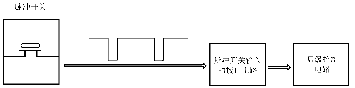
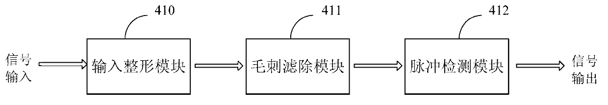
[0021] A pulse switch input interface circuit proposed by the present invention, such as figure 2 As shown, it includes an input shaping module 410 for shaping the pulse signal, a glitch filtering module 411 for filtering out the pulse signal determined as an interference signal, and a burr filtering module 411 for detecting the coming of a pulse to output a maintained level signal Pulse detection module 412, the input end of input shaping module 410 is connected with external pulse switch, to receive the pulse signal that external pulse switch outputs, the output end of input shaping module 410 is connected with the input end of burr filtering module 411, and burr filtering module The output terminal of 411 is connected to the input terminal of the pulse detection module 412, and the output terminal of the pulse detection module 412 is conne...


PUM


Abstract

The invention discloses a pulse switch input interface circuit, which comprises an input shaping module, a burr filtering module and a pulse detection module, wherein the input shaping module is used for carrying out shaping processing on pulse signals, the burr filtering module is used for filtering the pulse signals determined to be interference signals, the pulse detection module is used for detecting the pulse coming to output the maintained level signals, the input end of the input shaping module is connected with an external pulse switch for receiving the pulse signals output by the external pulse switch, the output end of the input shaping module is connected with the input end of the burr filtering module, the output end of the burr filtering module is connected with the input end of the pulse detection module, and the output end of the pulse detection module is connected with an external back-stage control circuit for outputting state signals required by the work of an external back-stage control circuit to the external back-stage control circuit. The pulse switch input interface circuit has the advantages that the circuit structure is simple, in addition, the interference pulse lower than the set pulse width can be filtered, and the pulse signals can be effectively converted into corresponding level signals required by the work of the back-stage control circuit.

Description

technical field [0001] The invention relates to a pulse signal processing circuit, in particular to an interface circuit for pulse switch input. Background technique [0002] Over the years, various pulse switches have been widely used in electronic circuits. Compared with traditional contact direct switches, pulse switches have the characteristics of low energy consumption and long life. high demands. [0003] The traditional circuit structure controlled by a pulse switch usually includes a pulse switch and a post-stage control circuit. The pulse switch directly transmits the pulse signal to the post-stage control circuit. The complexity of the post-stage control circuit is greatly reduced. In order to solve the problems existing in the traditional circuit structure controlled by the pulse switch, people in the industry proposed to set up an interface circuit between the pulse switch and the subsequent control circuit, such as figure 1 As shown, the pulse switch forms a...

Claims


Application Information

Patent Timeline
Patent Type & Authority Applications(China)
IPC IPC(8): H03K19/0185
Inventor 朱晓杰
Owner NINGBO SEMICON INT CORP
Why Eureka
Try Eureka