
Reducing agent aqueous solution mixing device and exhaust gas after-treatment device

A technology of mixing device and aqueous solution, which is applied in the direction of exhaust gas treatment, mixer, noise reduction device, etc., can solve problems such as insufficient ammonia, achieve the effects of suppressing back pressure, suppressing the increase of fuel consumption rate, and reducing flow path resistance

Active Publication Date: 2014-12-24
KOMATSU LTD
View PDF11 Cites 0 Cited by
  • Summary
  • Abstract
  • Description
  • Claims
  • Application Information

AI Technical Summary

Problems solved by technology

Therefore, the ammonia supplied to the reduction catalyst may be insufficient

Method used


Image

  • Reducing agent aqueous solution mixing device and exhaust gas after-treatment device
  • Reducing agent aqueous solution mixing device and exhaust gas after-treatment device
  • Reducing agent aqueous solution mixing device and exhaust gas after-treatment device

Examples


Embodiment Construction

[0055] [the whole frame]

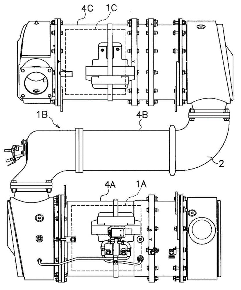
[0056] figure 1 It is a configuration diagram of the exhaust gas post-processing device 1 according to one embodiment of the present invention. The exhaust gas aftertreatment device 1 is sequentially provided with a diesel particulate filter (Diesel particulate filter: hereinafter referred to as "DPF") 1A, a urea aqueous solution mixing device 1B and Nitrogen oxide reduction catalyst (hereinafter referred to as "SCR") 1C. Each of the above-mentioned devices is installed in the middle of an exhaust pipe, and exhaust gas discharged from a diesel engine (not shown) through an exhaust manifold flows through the exhaust pipe.

[0057] DPF1A is a device for trapping particulate matter in exhaust gas, and is housed inside casing 4A.

[0058] The urea aqueous solution mixing device 1B is a device for adding an aqueous urea solution as a reducing agent to exhaust gas. The added urea aqueous solution is hydrolyzed to become ammonia, and the ammonia is supp...


PUM


Abstract

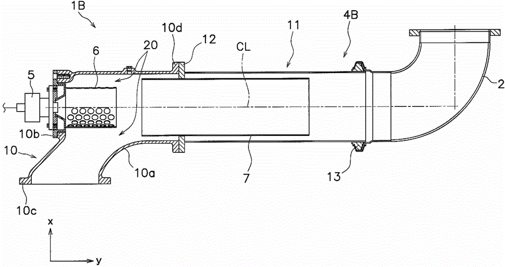
The present invention suppresses adhesion of a urea aqueous solution to an interior wall of an exhaust pipe and reduces flow resistance inside the exhaust pipe, in a urea aqueous solution mixing device. This urea aqueous solution mixing device is provided with an exhaust pipe (4B), an injector (5), a mixing pipe (6), an interior pipe (7), and a flow unit (20). The exhaust pipe (4B) has an elbow part (10) with a curved section, and a straight part (11). The injector (5) injects the urea aqueous solution, and is provided in the elbow part (10). The mixing pipe (6) is positioned so as to cover the area around the urea aqueous solution injected by the injector (5), and has an exit part formed between the interior walls of the exhaust pipe (4B) with an interval interposed therebetween, and a plurality of openings (6a) formed in the outer-peripheral surface thereof. The interior pipe (7) allows exhaust gas to flow through the interior and outer-peripheral sections thereof, and is positioned in the straight part (11) of the exhaust pipe (4B). The flow unit (20) guides exhaust gas into the interior pipe (7), and is formed between the exit part of the mixing pipe (6) and the interior walls of the exhaust pipe (4B).

Description

technical field [0001] The present invention relates to a reductant aqueous solution mixing device, in particular to a device which is arranged in parallel with the filter between a filter for trapping particulate matter in exhaust gas and a reduction catalyst for reducing and purifying nitrogen oxides in exhaust gas. A reducing agent aqueous solution mixing device for adding a reducing agent aqueous solution to exhaust gas. In addition, the present invention also relates to an exhaust gas post-treatment device comprising the above-mentioned reducing agent aqueous solution mixing device. Background technique [0002] Engine exhaust contains nitrogen oxides (NOx). In order to suppress the release of the nitrogen oxides into the atmosphere, an exhaust after-treatment device is installed in the middle of the exhaust path. The exhaust gas post-processing device includes: a filter, which traps particulate matter in the exhaust gas; a urea aqueous solution mixing device, which i...

Claims


Application Information

Patent Timeline
Patent Type & Authority Patents(China)
IPC IPC(8): F01N3/24B01D53/94F01N3/08F01N3/28
CPCF01N3/2892B01D53/90F01N3/2066F01N2610/1453Y02T10/24F01N2240/20B01D53/9409F01N2470/02B01D2251/2067F01N2610/02Y02T10/12B01F23/2132B01F2025/931B01F25/313F01N3/28F01N3/035B01D53/94
Inventor 饭岛正木泽宏史伊东木辻村真治加藤隆志折田哲生并松宽仁原一生富冈裕之
Owner KOMATSU LTD
Learn More