Fixture for turning thin aluminum valve plate

A technology for processing thin plates and aluminum valve plates, which is applied in the direction of manufacturing tools, metal processing equipment, metal processing machinery parts, etc. It can solve the problems of difficult control, valve plates exceeding the error range, product bending deformation, etc., to achieve compact design, reduce Overhang length, the effect of increasing rigidity

Inactive Publication Date: 2013-09-11
ZHEJIANG SHANHAI MACHINERY
View PDF5 Cites 3 Cited by
  • Summary
  • Abstract
  • Description
  • Claims
  • Application Information

AI Technical Summary

Problems solved by technology

The material of the valve plate generally includes cast iron and aluminum alloy. Some cast iron valve plates are processed by surface grinding process. After grinding one side, turn over and grind the other side. Because the electromagnetic chuck is used for clamping tools, many products have bending deformation after the workpiece is released. The phenomenon, using the knife-edge ruler and feeler gauge to detect the flatness can be found to exceed the error range
Compared with the cast iron valve plate, the flatness and parallelism of the thin aluminum valve plate are more difficult to control. If the direction of the clamping force is not selected properly, the flatness of the processed valve plate will seriously exceed the error range, which will affect the air compressor. For the working performance of the whole machine, the blank of the thin aluminum valve plate is die-cast. The thin aluminum valve plate cannot be clamped on the electromagnetic chuck of the surface grinder, and the blank itself cannot be clamped by vacuum. How to clamp the workpiece correctly is To solve the difficulty of valve plate turning, the grinding wheel of the grinding machine is also easy to bite into the workpiece when grinding is used, which will easily cause poor surface roughness

Method used


Image

  • Fixture for turning thin aluminum valve plate
  • Fixture for turning thin aluminum valve plate

Examples


Embodiment

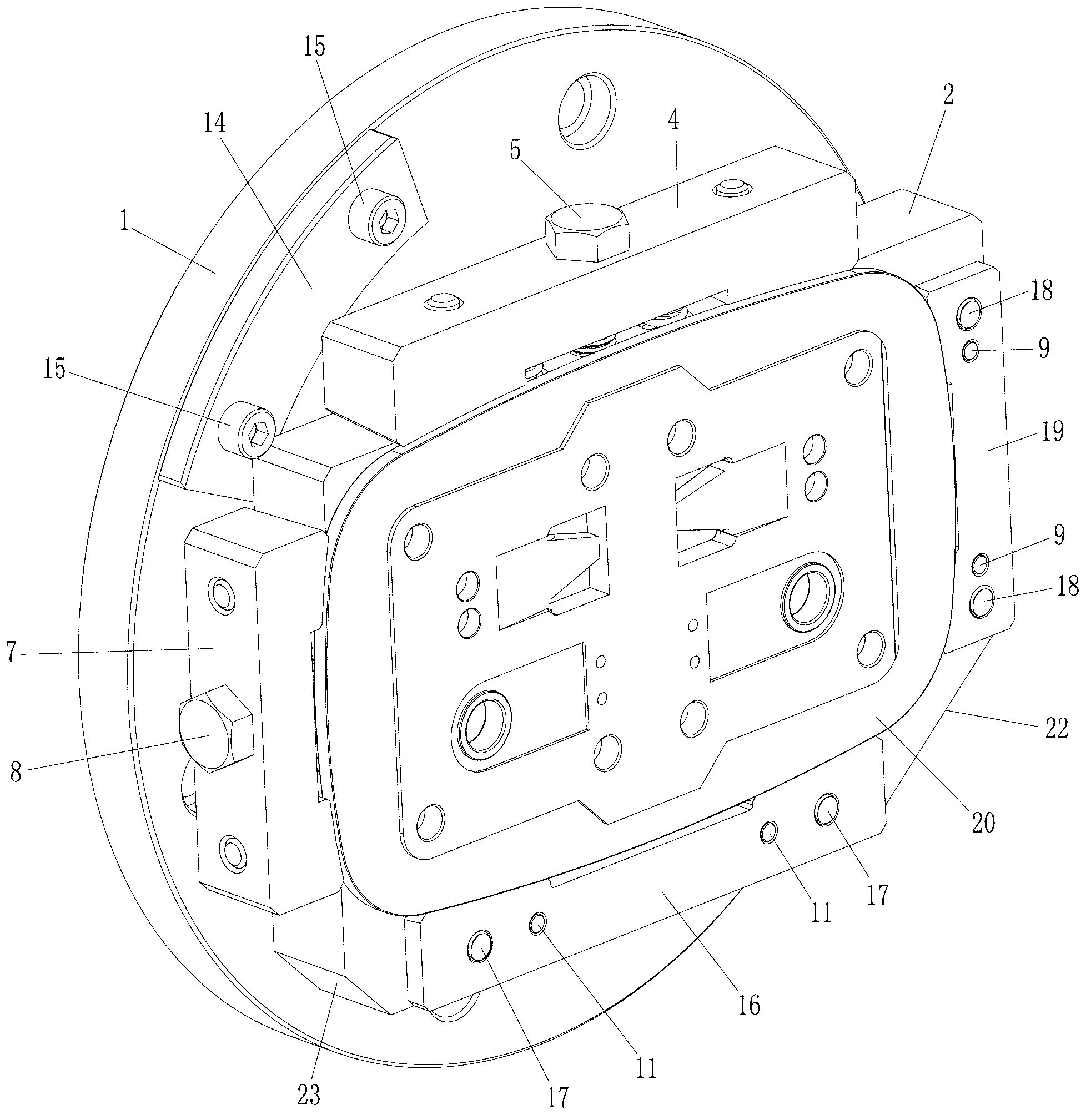
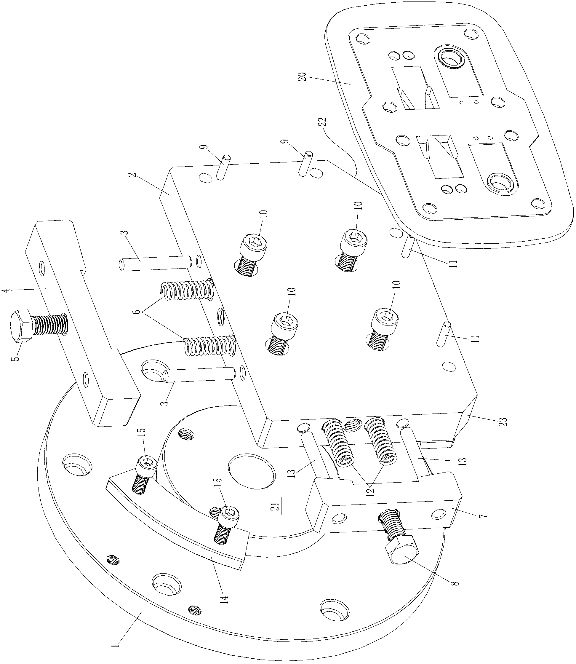
[0014] Example: see figure 1 and figure 2 , the present invention is connected to the main shaft of the CNC lathe via the flange chassis 1, the flange chassis 1 is universally matched with the three-jaw chuck flange of the CNC lathe, the material is HT200, and the positioning seam tire 21 of the flange chassis 1 is passed through four M10 inner hexagonal main board fixing screws 10 are connected and fixed with the rectangular valve plate positioning main board 2. The positioning plane of the valve plate positioning main board 2 is perpendicular to the center line of the lathe spindle. The positioning plane of the valve plate positioning main board 2 is flattened by turning with a turning tool, and it is not necessary to level the positioning plane in the future to ensure the perpendicularity of the positioning plane and the spindle of the CNC lathe. The valve plate positioning main board 2 deviates from the center of the flange chassis 1 downwards and to the right. The lower...


PUM


Abstract

A fixture for turning a thin aluminum valve plate comprises a flange bottom connected with a spindle of a digital controlled lathe. A rectangular main positioning plate of the valve plate is fixedly connected to a positioning spigot tire of the flange bottom, and is arranged deviating the center of the flange bottom right-off and downwards. The left lower corner of the main positioning plate of the valve plate is provided with a small chamfer, and the right lower corner of the main positioning plate of the valve plate is provided with a large chamfer. A longitude fixed clamping plate is arranged on the upper right edge of the outer side of the main positioning plate of the valve plate, and a transverse fixed clamping plate is arranged on the upper lower edge of the outer side of the main positioning plate of the valve plate. A longitude movable clamping plate is arranged on the left end face of the main positioning plate of the valve plate, and a transverse movable clamping plate is arranged on the upper side end face of the main positioning plate of the valve plate. The outer side faces of the longitude movable clamping plate and the transverse movable clamping plate are flush and are slightly lower than the plane to be machined of the thin aluminum valve plate. The thin aluminum valve plate is clamped radially, the fixture is safe and reliable, products have well flatness after machining, and the requirement of processing technology of the products can be guaranteed.

Description

technical field [0001] The invention belongs to the technical field of machining tooling fixtures, in particular to a tooling fixture for turning and processing thin aluminum valve plates. Background technique [0002] The valve plate is an important part of the valve group on the cylinder head of the air compressor. The valve plate is installed on the upper part of the cylinder, and the valve plate with high airtightness is installed on the notch on the valve plate to realize the opening and sealing during work. Therefore, the surface finish, flatness and roughness of the valve plate have strict technical requirements. The material of the valve plate generally includes cast iron and aluminum alloy. Some cast iron valve plates are processed by surface grinding process. After grinding one side, turn over and grind the other side. Because the electromagnetic chuck is used for clamping tools, many products have bending deformation after the workpiece is released. If the flatne...

Claims


Application Information

Patent Timeline
Patent Type & Authority Applications(China)
IPC IPC(8): B23Q3/12
Inventor 占长安
Owner ZHEJIANG SHANHAI MACHINERY
Why Eureka
Try Eureka