Bobbin shunt-wound machine

A separate winding and bobbin technology, which is used in the transportation of filamentous materials, thin material handling, transportation and packaging, etc., can solve the problems of low winding efficiency and uneven winding, so as to improve the winding efficiency and ensure the safety of the winding environment. Effect

Inactive Publication Date: 2013-09-11
HAINING SHENGXIANG WIRE
View PDF6 Cites 5 Cited by
  • Summary
  • Abstract
  • Description
  • Claims
  • Application Information

AI Technical Summary

Problems solved by technology

However, most of the existing bobbin winding machines have problems such as uneven winding and low winding efficiency.

Method used


Image

  • Bobbin shunt-wound machine
  • Bobbin shunt-wound machine
  • Bobbin shunt-wound machine

Examples


Embodiment 1

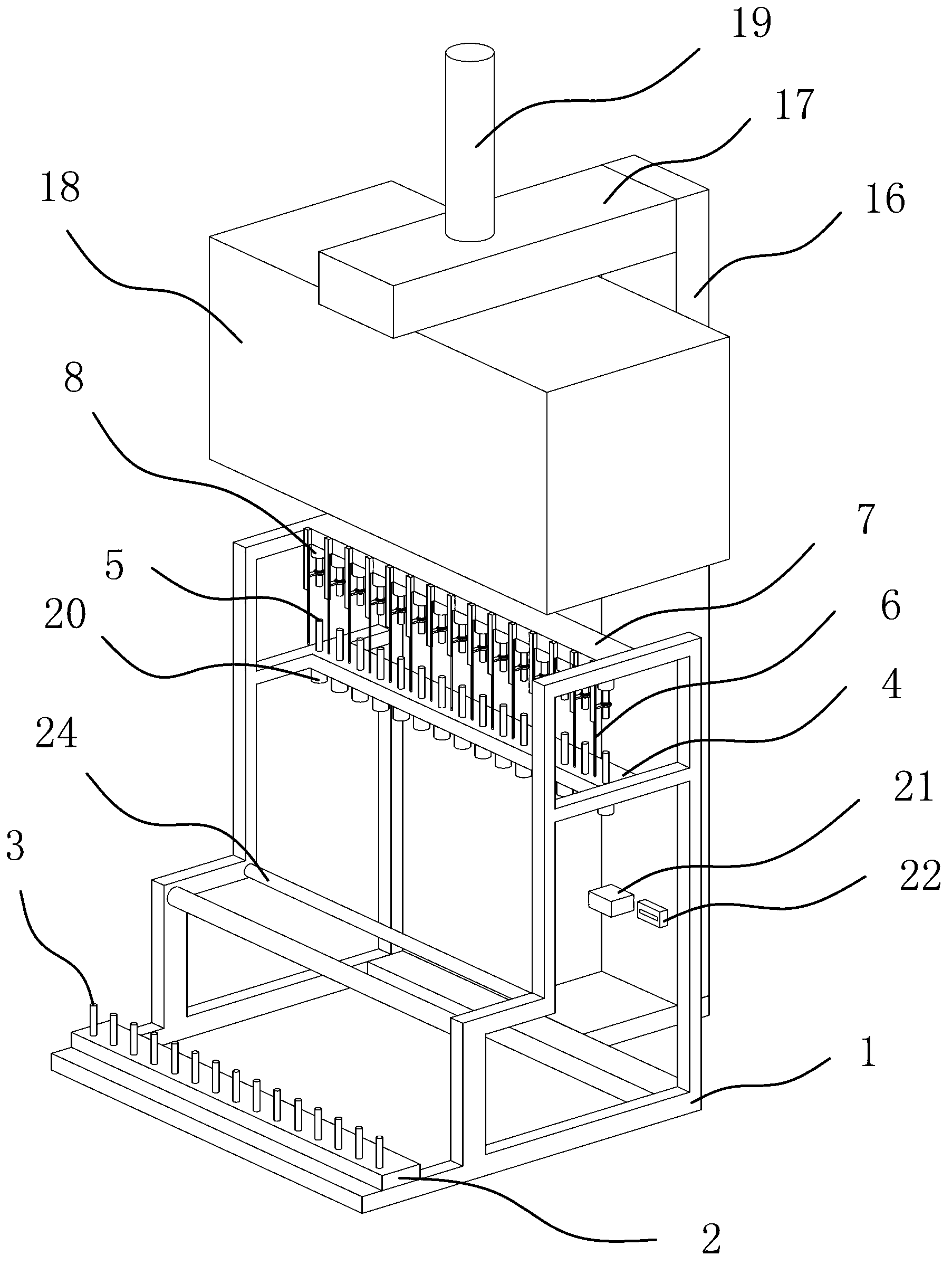
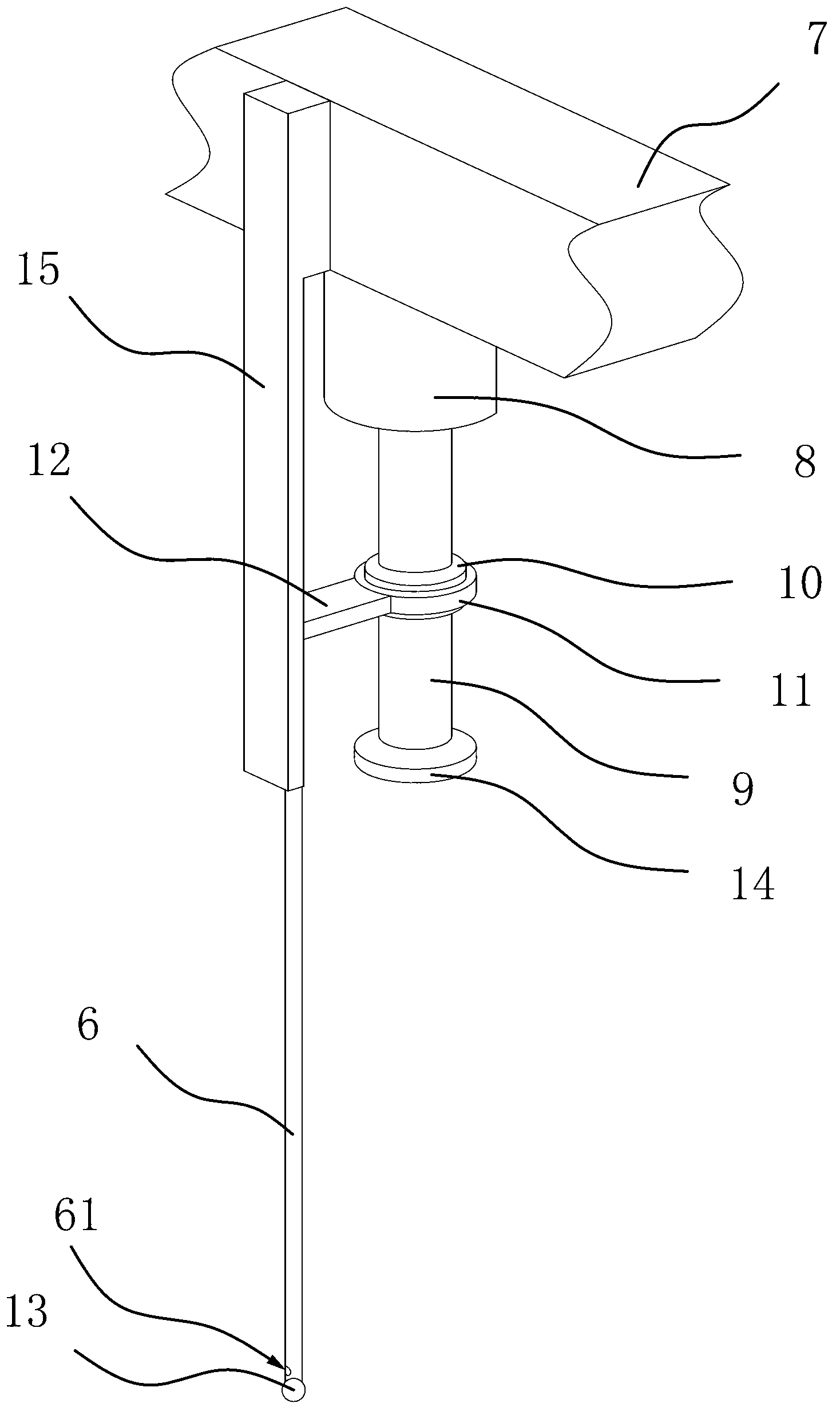
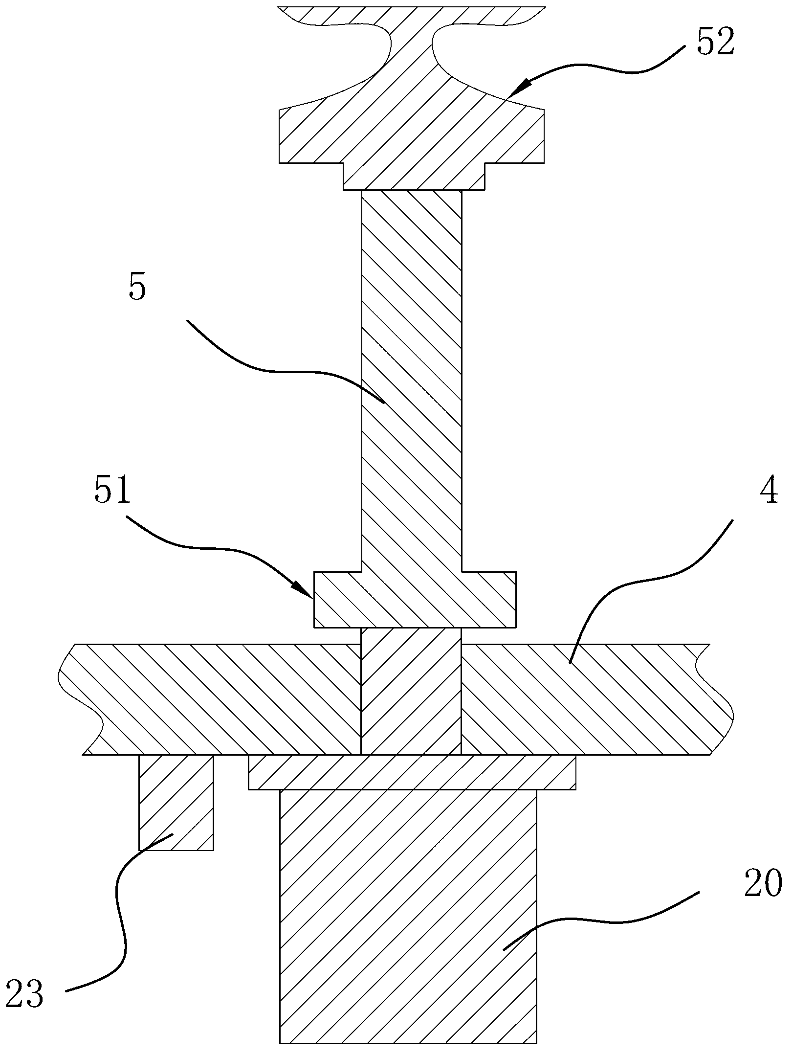
[0028] Such as figure 1 As shown, a bobbin winding machine includes a frame 1, on which a mounting plate 2 and a mounting plate 4 are fixed, and the mounting plate 2 4 is located obliquely above the mounting plate 2, and the mounting plate 2 There are a number of inserting rods 13 for placing the main line barrel fixed on the top, and a number of inserting rods 5 for placing the auxiliary line barrels are arranged on the mounting plate 24, and one end of the inserting rod 25 is provided with a drive inserter The driving mechanism for the rotation of the rod two 5, the other end of the insertion rod two 5 is the insertion end, between the insertion rod one 3 and the insertion rod two 5, there is a thread that can guide the yarn on the insertion rod one 3 into the insertion Lead rod 6 on the rod two 5, lead rod 6 is arranged in parallel with insertion rod two 5, and one end of lead rod 6 offers a through hole 61 that can pass through for yarn, and lead rod 6 is also provided wit...

Embodiment 2

[0035] The structure and principle of this embodiment are basically the same as the first embodiment, the difference is that in the second embodiment, the telescopic mechanism includes a cylinder one, and one end of the guide rod 6 is fixed on the piston rod of the cylinder one, and the mounting plate two 4 is fixed with a fixed plate directly above, and cylinder one is fixed on the fixed plate, and the piston rod of cylinder one is vertically downward. When the cylinder works, the cylinder will drive the piston rod back and forth to expand and contract, and at the same time it can also drive the guide rod 6 fixed on the piston rod to expand and contract back and forth, and the head of the guide rod 6 will go back and forth in the corresponding winding area on the secondary bobbin Move, so that the yarn is evenly wound on the secondary bobbin.


PUM


Abstract

The invention provides a bobbin shunt-wound machine and belongs to the technical field of textile. The bobbin shunt-wound machine solves the problems that an existing bobbin shunt-wound machine is uneven in yarn winding, low in winding efficiency and the like in the prior art. The bobbin shunt-wound machine comprises a rack, wherein a first installation plate and a second installation plate are fixed on the rack, a plurality of first bobbin inserting rods which are used for holding main bobbins are fixed on the first installation plate, a plurality of second bobbin inserting rods which are used for holding auxiliary bobbins are arranged on the second installation plate, one end of each second bobbin inserting rod is provided with a driving mechanism which drives the second bobbin inserting rod to rotate, the other end of the second bobbin insertion rod is the inserting end, a yarn guide rod is arranged between each first bobbin inserting rod and one second bobbin inserting rod, each yarn guide rod can lead yarn arranged on one first bobbin inserting rod to one second bobbin inserting rod, each yarn guide rod and each bobbin inserting rod are parallel, one end of each yarn guide rod is provided with a through hole which allows yarn to pass through, and a stretching and retracting mechanism is arranged on each yarn guide rod and can drive the yarn guide rod to move upward and downward. The bobbin shunt-wound machine has the advantages of being even in yarn winding and high in efficiency of yarn winding.

Description

technical field [0001] The invention belongs to the technical field of textiles, and relates to a winding machine for wire cylinders. Background technique [0002] Yarn is a continuous linear object made of various textile fibers. It is thin and soft, and has the basic properties required for textile processing and final product use. Yarn is mainly used for weaving woven fabrics, knitted fabrics, knitted fabrics and some non-woven fabrics, and a small part exists directly in the form of linear textiles, such as various sewing threads, plush threads, embroidery threads, cords and other miscellaneous threads , it is an essential raw material in the textile industry and garment industry. [0003] When the yarn is bought from the market, the yarn is usually wound on the bobbin. Such a bobbin not only has a large number of coil turns, but also has a large volume, and if it is directly used on the product, it is also prone to tearing. knot phenomenon. Therefore, people must sep...

Claims


Application Information

Patent Timeline
Patent Type & Authority Applications(China)
IPC IPC(8): B65H54/02B65H54/70B65H54/74B65H57/26
Inventor 陈晔
Owner HAINING SHENGXIANG WIRE
Why Eureka
Try Eureka