Bladeless fan turbine device with splitter blades

A technology of splitting blades and bladeless fans, which is applied to the components of pumping devices for elastic fluids, non-variable pumps, machines/engines, etc., which can solve the complex flow conditions of bladeless fans and reduce the overall cost of bladeless fans Performance, turbocharger performance degradation and other issues, to achieve the effect of improving operational stability, reducing overall noise, and increasing pressure ratio

Inactive Publication Date: 2013-09-11
ZHEJIANG SCI-TECH UNIV
View PDF6 Cites 14 Cited by
  • Summary
  • Abstract
  • Description
  • Claims
  • Application Information

AI Technical Summary

Problems solved by technology

The turbines of bladeless fans that are widely used at present all adopt uniform long blades. When the air flow flows through the flow channel of the two long blades, the separation phenomenon of backflow and flow is easy to form in the second half of the flow channel, which will increase the speed of the turbine. The pressure performance is reduced, the efficiency is reduced, and the internal flow conditions of the bladeless fan become complicated, thereby reducing the overall performance of the bladeless fan

Method used


Image

  • Bladeless fan turbine device with splitter blades
  • Bladeless fan turbine device with splitter blades
  • Bladeless fan turbine device with splitter blades

Examples


Embodiment 1

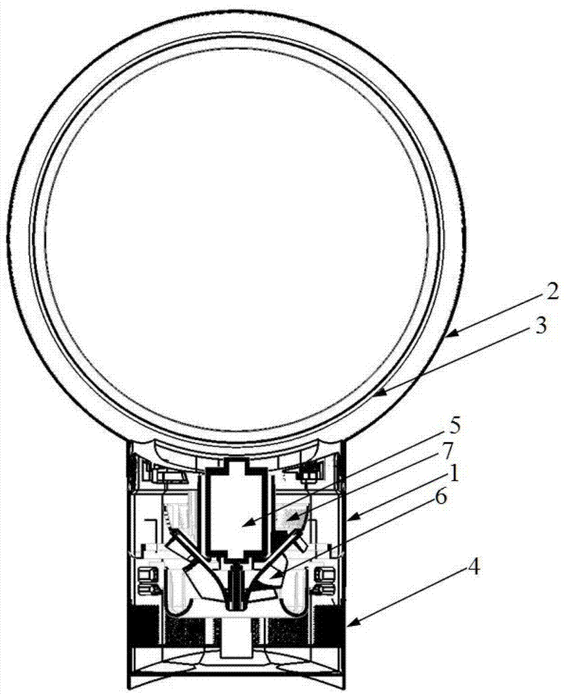
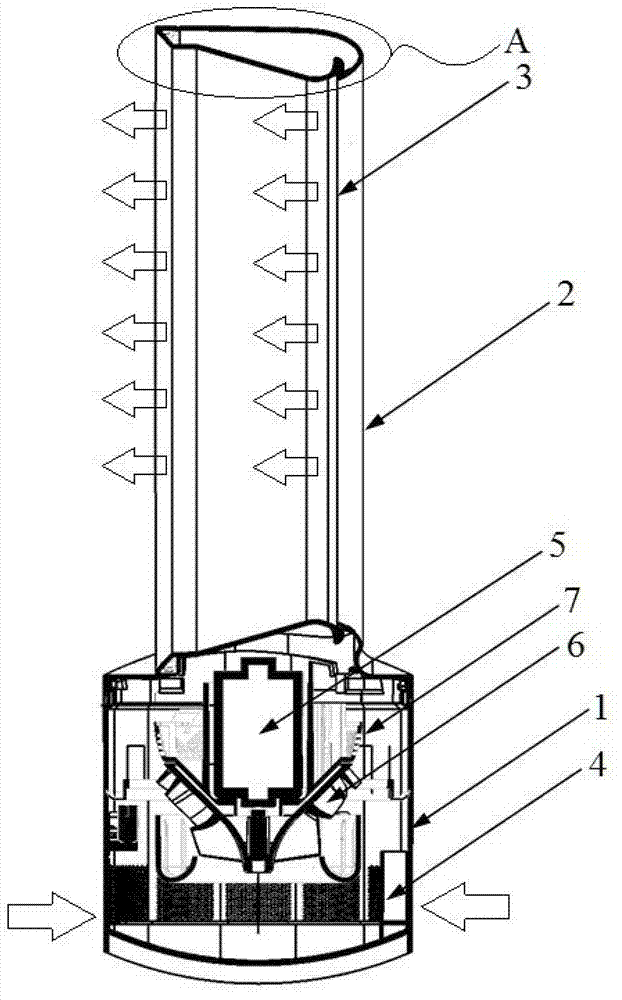
[0049] Such as figure 2 , Figure 9 As shown, the inlet end of the splitter vane turbine 6 is facing downward, and the outlet end is upward, and the airflow enters from the air inlet 4 horizontally. After the supercharging effect of the splitter vane turbine 6, the airflow enters the air outlet ring 2 vertically upwards, and then flows from the air outlet ring The air outlet 3 on the 2 flows out along the Coanda surface.

Embodiment 2

[0051] Such as Figure 10 , Figure 11 As shown, another kind of splitter vane turbine 6 is proposed in this embodiment, and this splitter vane turbine 6 adopts the blade layout form of intersecting distribution of long, medium and short blade intervals; the splitter vane turbine 6 includes an inner ring wall 8, long blades 9. The middle vane 21 and the short vane 11. The middle vane 21 is the splitter vane 10 in the above-mentioned embodiment. In order to further highlight the ability of the splitter vane 10 to improve the performance of the overall device, the splitter vane can be added on the basis of the above-mentioned embodiment, namely In the present embodiment, short blades 11 are added to the flow channels of middle blades 21 and long blades 9, where the outlet radii of long blades 9, middle blades 21 and short blades 11 are all the same, and the inlet radii from large to small are as follows: short Blade 11, middle blade 21, long blade 9, the ratio of the inlet radi...


PUM


Abstract

The invention discloses a bladeless fan turbine device with splitter blades. The bladeless fan turbine device with the splitter blades comprises a motor, a motor fixing device, a splitter blade turbine and an outer ring wall. A motor rotating shaft penetrates through the motor fixing device and is connected with the inner side of the inner ring wall of the splitter blade turbine. The inner side of the outer ring wall is sleeved on the splitter blade turbine. The splitter blade turbine comprises the inner ring wall, long blades and splitter blades, wherein the long blades are arranged in the peripheral direction of the inner ring wall, the splitter blades are located between every two adjacent long blades respectively and are distributed on the inner ring wall in the peripheral direction, the outlet diameters of the splitter blades equal those of the long blades, and the inlet diameters of the splitter blades differ from those of the long blades. The bladeless fan turbine device with the splitter blades is located in a bladeless fan base. Pressurizing ability and pressurizing efficiency of the bladeless fan turbine device with the splitter blades are effectively improved, service life of the bladeless fan turbine device with the splitter blades is prolonged, and therefore air-out amount of a bladeless fan is increased, operation stability is improved, noises of the bladeless fan are reduced, overall performance of the bladeless fan is improved, and the bladeless fan has the advantages of saving energy and protecting the environment.

Description

technical field [0001] The invention belongs to the technical field of fans, in particular to a bladeless fan turbine device with splitter blades. Background technique [0002] As a main heat dissipation and ventilation equipment, fans are indispensable in daily life. The current household fans are mainly composed of brackets, motors and fan blades. In order to prevent the fan blades from being easily touched by hands when the fan is working, a For safety considerations, a protective cover is added to the traditional fan. But the commonly used protective cover can not play a good protective effect on children; at the same time, due to the number of fan blades, the wind blown by the traditional fan is not natural wind, which makes people always feel a sense of collision and makes the human body feel uncomfortable. [0003] In order to solve these problems, a British patent with publication number GB2452490A on March 11, 2009 proposes a new type of fan, which is a bladeless f...

Claims


Application Information

Patent Timeline
Patent Type & Authority Applications(China)
IPC IPC(8): F04D29/28F04D29/30
Inventor 金英子朱立夫吴泳敏胡勇军李国琪
Owner ZHEJIANG SCI-TECH UNIV
Why Eureka
Try Eureka