Method for utilizing rolling friction to centralize piston rod to do reciprocating motion and actuating device for utilizing rolling friction to centralize piston rod to do reciprocating motion through implementing method

A technology of rolling friction and reciprocating motion, applied in the field of rolling friction righting piston rod reciprocating motion, rolling friction righting piston rod reciprocating motion driving device

Inactive Publication Date: 2013-09-11
刘素华
View PDF17 Cites 23 Cited by
  • Summary
  • Abstract
  • Description
  • Claims
  • Application Information

AI Technical Summary

Problems solved by technology

However, if the seal is too thick, it will cause a large friction between the cylinder body and the seal. If the seal is thin, it will be difficult to withstand the large breaking force of the cylinder rod, which will easily make the service life of the drive device short. The connection of the moving parts prevents the cylinder rod from being separated within a certain range through the rotation of the shaft, but when the hinge shaft cannot rotate due to corrosion, twisting, etc., it will cause a large separation of the cylinder rod, and the twisting of the cylinder rod cause damage to the drive

Method used


Image

  • Method for utilizing rolling friction to centralize piston rod to do reciprocating motion and actuating device for utilizing rolling friction to centralize piston rod to do reciprocating motion through implementing method
  • Method for utilizing rolling friction to centralize piston rod to do reciprocating motion and actuating device for utilizing rolling friction to centralize piston rod to do reciprocating motion through implementing method
  • Method for utilizing rolling friction to centralize piston rod to do reciprocating motion and actuating device for utilizing rolling friction to centralize piston rod to do reciprocating motion through implementing method

Examples


Embodiment 1

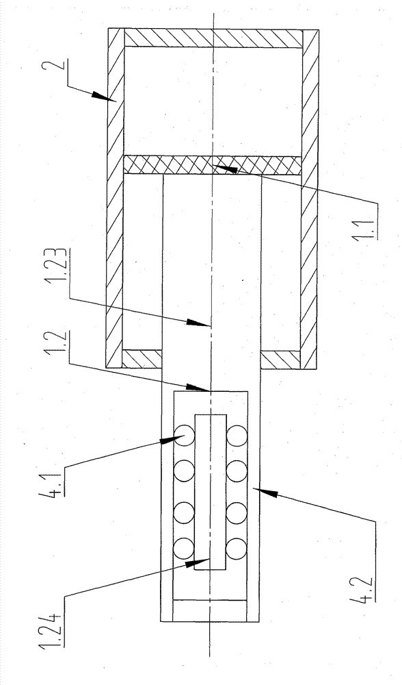
[0136] figure 1 It is the centralizer hydraulic drive device described in Embodiment 1, which includes a piston rod 1, a cylinder body 2, and a control member 3. The device also includes a centralizer 4, and the centralizer 4 includes a guide rolling body 4.1 and a guide rolling body support 4.2 , the guide rolling body support 4.2 is integrated with the cylinder body 2, the piston rod 1 includes the piston 1.1, the cylinder rod 1.2, the piston 1.1 is connected separately with the cylinder rod 1.2, the piston 1.1 is arranged in the cylinder body 2, between the piston and the cylinder body A seal is provided, and the guide rolling body 4.1 is arranged between the guide rolling body support 4.2 and the cylinder rod 1.2. Under the control of the control part 3, the piston 1.1 drives the cylinder rod 1.2 to reciprocate, and the guide rolling body 4.1 fits the guide rolling body The support member 4.2 and the cylinder rod 1.2 rotate to straighten the movement direction of the cyli...

Embodiment 2

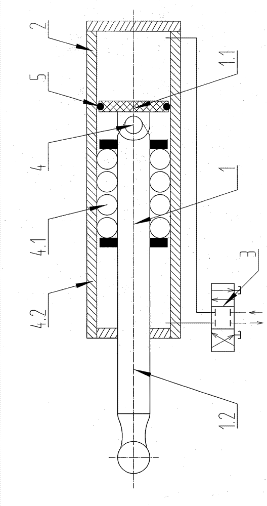
[0144] figure 2 It is the centralizer hydraulic drive device described in Example 2, the guide rolling element support 4.2 is separated from the cylinder body 2, the guide rolling element 4.1 is arranged outside the cylinder body 2, the piston 1.1 and the cylinder rod 1.2 are integrated, and the piston 1.1 There is a piston rolling body 6 between the cylinder body 2, the piston 1.1 is separated from the piston rolling body 6, the piston rolling body 6 is separated from the guide rolling body 4.1, and the piston rolling body 6 supports the rolling friction reciprocating motion of the piston 1.1 and the cylinder body 2 , The sealing element 5 is arranged at both ends of the piston rolling body 6, and the sealing element 5 can play a sealing role, but not a supporting role.

[0145] The piston rolling body 6 can be arranged around the piston 1.1 or on one side of the piston 1.1 or on two or more sides of the piston 1.1.

[0146] The piston 1.1 and the piston rolling body 6 can ...

Embodiment 3

[0149] image 3 It is the centralizer hydraulic drive device described in Embodiment 3, the guide rolling element support 4.2, the cylinder rod 1.2 includes a limit structure 7, the limit structure 7 is a guide rolling element limit structure, and the guide rolling element 4.1 is arranged on the guide rolling element Body limiting structure, the guiding rolling body limiting structure limits the rolling space of the guiding rolling body 4.1.

[0150] The guide rolling body limiting structure is the raceway 7.1, which can also be a recirculating raceway or a barrel or a pit or a reciprocating stroke section or a cage or a limiting plate or a limiting ring or a limiting sleeve or a limiting platform or Limit rod or limit shaft or limit groove or spherical convex or boss or bearing or inner body and outer sleeve or oval or dumbbell-shaped or cylindrical or conical or circular or roller or table-shaped column or table-shaped ball Or table-shaped drum or groove-shaped column or gr...


PUM


Abstract

The invention belongs to the field of machinery, and relates to a hydraulic drive, gas drive or solid flowing pressure drive device and equipment, particularly to a method for utilizing rolling friction to centralize a piston rod to do reciprocating motion and an actuating device for utilizing rolling friction to centralize the piston rod to do reciprocating motion through implementing the method. The actuating device comprises a piston rod, a cylinder body, a controlling piece and a centralizer, wherein the piston rod comprises a piston and a cylinder rod; the centralizer comprises a guiding rolling element and a guiding rolling element supporting piece; the guiding rolling element is arranged between the guiding rolling element supporting piece and the cylinder rod; the controlling piece controls flow of liquid, gas or solid; the piston drives the cylinder rod to do reciprocating motion; and the guiding rolling element fits the guiding rolling element supporting piece and the cylinder rod to rotate and centralizes the motion direction of the cylinder rod through the rolling friction.

Description

technical field [0001] The invention belongs to the field of machinery and can be used for hydraulically driven or pneumatically driven or solid flow pressure driven devices and equipment, and is especially suitable for a method for reciprocating motion of a rolling friction righting piston rod in the mining field and a rolling friction righting piston rod reciprocating drive for implementing the method device. Background technique [0002] Existing hydraulic drive or pneumatic drive or solid flow pressure drive, especially hydraulic drive or pneumatic drive or solid flow of existing excavators, shearers, roadheaders, loaders, hydraulic supports, etc. Pressure driving device, its structure is cylinder body, piston, cylinder rod, seal, control parts, etc., the piston is set in the cylinder body, under the control of the control part, the piston drives the cylinder rod to move linearly, and the cylinder body supports the cylinder through the seal Therefore, when the cylinder...

Claims


Application Information

Patent Timeline
Patent Type & Authority Applications(China)
IPC IPC(8): F15B15/14
Inventor 刘素华
Owner 刘素华
Why Eureka
Try Eureka