

A Release Mechanism for Dual Control Aircraft Control System
A technology for aircraft control and active parts, applied in mechanical equipment, automatic clutches, clutches, etc., can solve problems such as unstable release torque value, reduced pressing force, broken chips falling between the driving disc and the driven disc, etc. , to achieve the effect of improving working stability and service life, little influence of temperature and humidity, and strong environmental adaptability
Active Publication Date: 2016-01-20
XIAN AIRCRAFT DESIGN INST OF AVIATION IND OF CHINA
View PDF5 Cites 0 Cited by
- Summary
- Abstract
- Description
- Claims
- Application Information
AI Technical Summary
Problems solved by technology
[0003] At present, among the mechanical release mechanisms, there are mainly friction plate release mechanisms, jaw type release mechanisms, and shear pin type release mechanisms. The friction plate release mechanism is composed of multi-layer friction plates. The friction plate is pressed tightly to realize the connection function. When it needs to be released, the pressing force is reduced to realize the release. It is mainly used in the automobile industry to realize the release and connection between the engine and the gearbox. This type of release mechanism cannot achieve accurate Angular displacement transmission function
The interlocking release mechanism is formed by two sets of toothed gear members with convex teeth. The two convex teeth are in the shape of a slope. When the two sets of toothed teeth are engaged and the transmission torque is greater than the frictional force of the engagement, the toothed wheels will slip and release each other. However, when the transmission torque decreases, the release mechanism is connected again. At the same time, due to the machining accuracy, the material of the toothed wheel and the external temperature, there will be a gap in the positive and negative movement of the jaw-type release mechanism. The release torque value is unstable and cannot The active part and the driven part are completely released after the release
The shearing safety pin release mechanism is composed of a driving disc, a driven disc and a safety pin. The safety pin is inserted into the pin hole on the driving disc and the driven disc. When the torque of the driving disc and the driven disc is greater than the shear strength value of the safety pin , the pin is cut off, and the release torque value of this type of release mechanism is unstable. After cutting, it will scratch the driving disc or the driven disc, or there will be broken chips falling between the driving disc and the driven disc, and the complete release cannot be achieved. You need to replace the safety pin to restore, and it cannot be restored in working condition
Method used
View moreImage
Smart ImageViewing Examples

Examples
Embodiment 1
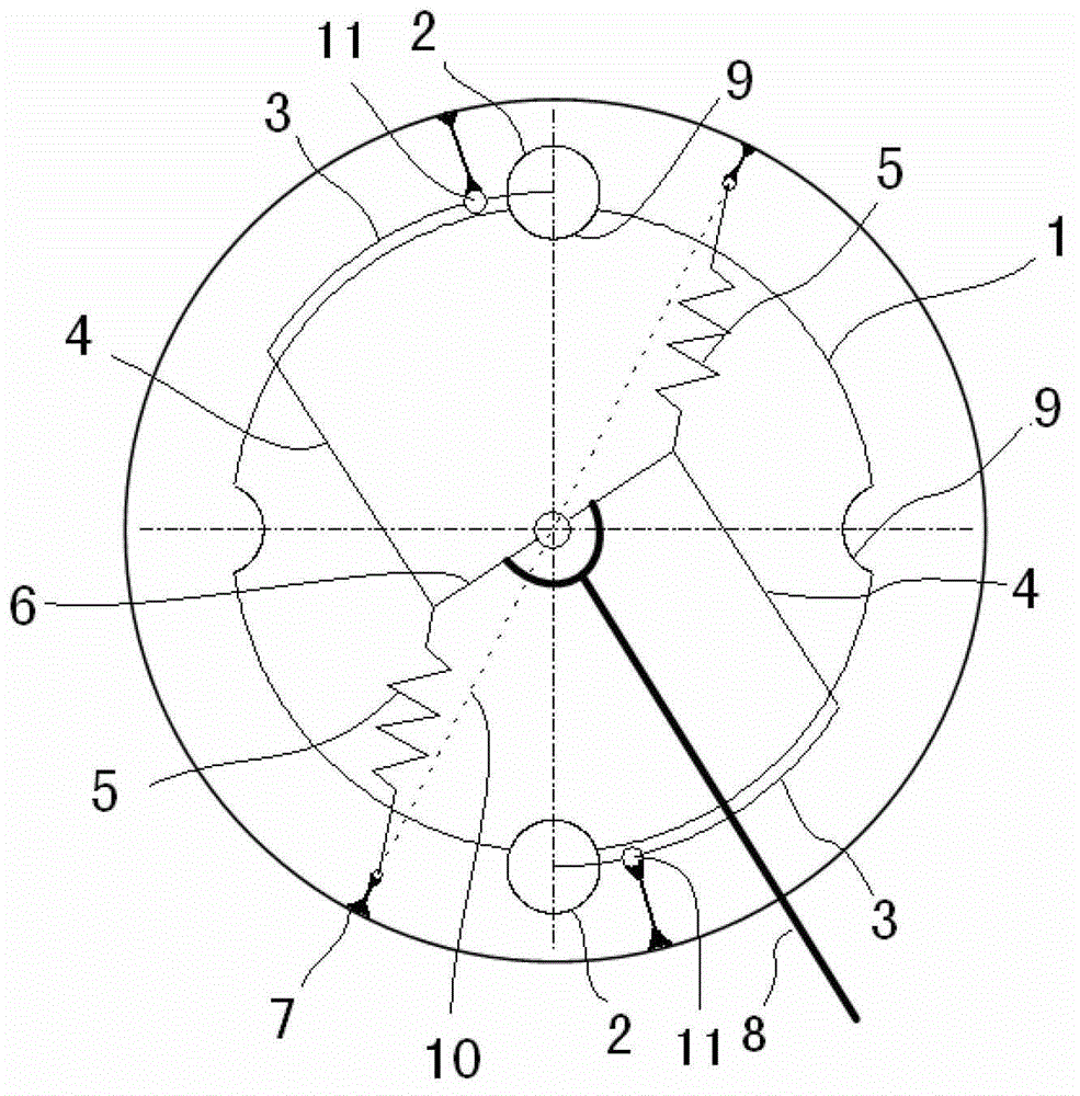
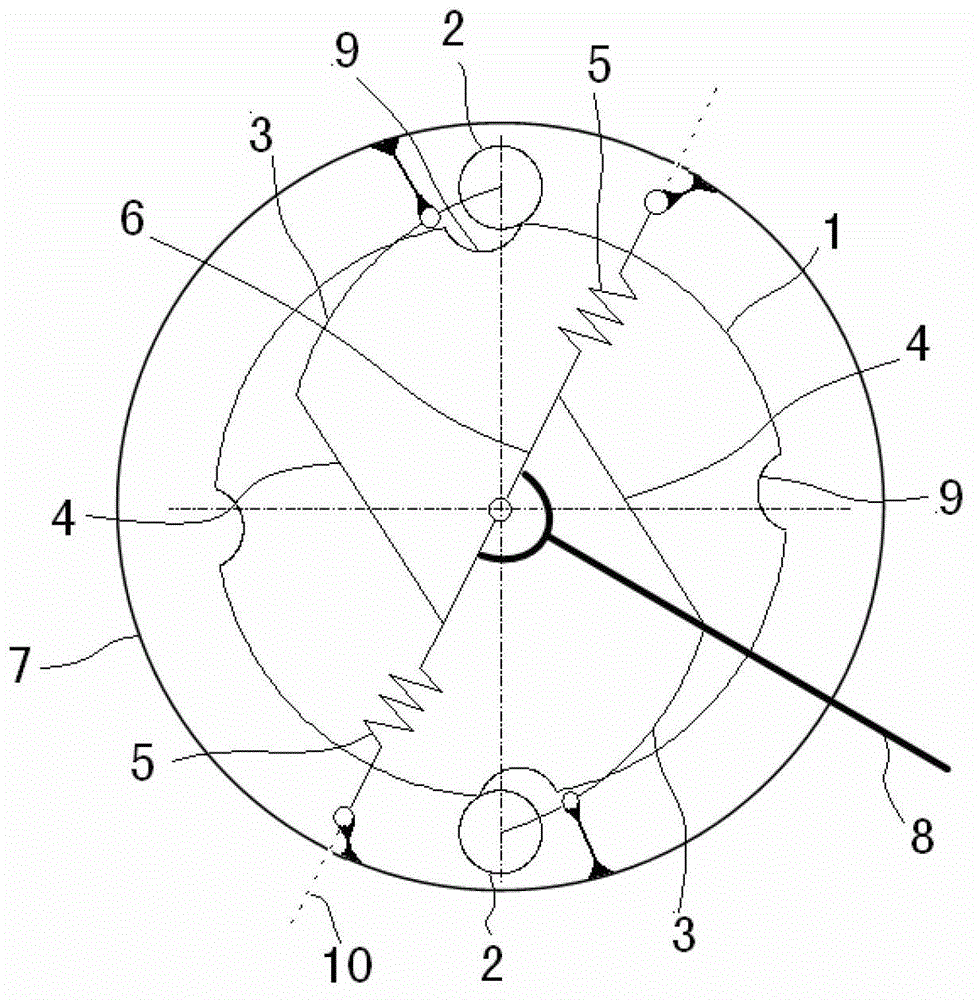
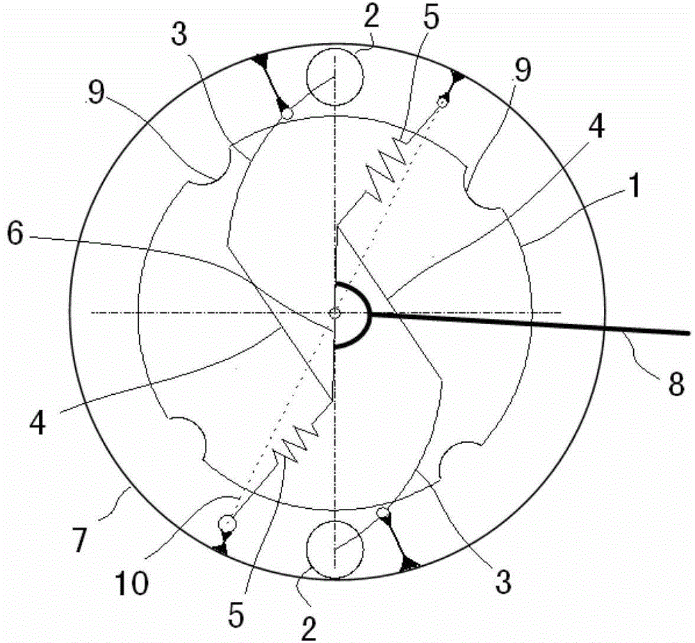
[0027] Such as Figure 4 As shown, in this embodiment, according to actual needs, an assembly consisting of 4 sets of springs and two sets of push rods 3, rollers 2 and connecting rods 4 are provided.
Login to View More PUM
 Abstract
The invention belongs to the field of aviation machinery design and particularly relates to a dual-control fight control system releasing mechanism comprising a driving component and a driven component. The driving component comprises a cam which is round, and the outside of the cam is provided with a circular groove. The driven component comprises a roller, a push bar, a connecting bar, a spring, a rocker, a case and a shift bar. Rotational motion can be accurately transmitted between the driving component and the driven component, a positive-reverse motion gap guarantees no evident reversing gap when positive direction and reverse direction are switched; a spring mechanism in the releasing mechanism guarantees through release between the driving part and the driven component after releasing, and guarantees mutual immunization between the driving component and the driven component after releasing. The dual-control fight control system releasing mechanism has the advantages that the mechanism is simple in structure and high in reliability as being implemented by a reliable plane link mechanism, has low requirements on materials, guarantees small abrasion of parts, is less susceptible to temperature and humidity and is high in environmental adaptivity; re-linking can be achieved by simple operation after releasing, releasing is non-destructive, demounting or overhaul is not needed, and the service life is long.
Description
Technical field [0001] The invention belongs to the field of aviation machinery design, and specifically relates to a release mechanism of a dual-control aircraft control system. Background technique [0002] In the field of mechanical design, especially the design direction of rotating drive mechanism, it involves the use of a fixed torque release mechanism. Due to actual working conditions, the requirements are: 1. The drive and the follower are required to transmit accurate rotation Movement, and the forward and reverse clearance requirements are strict; 2. When the machine fails or the load reaches a certain value, the linkage between the driving part and the follower is automatically disconnected, and the driving part and the follower are required to be disconnected Complete release without mutual influence; 3. The requirement is a purely mechanical release mechanism; 4. After the release mechanism is released, the release mechanism can be connected again according to the ac...
Claims
Login to View More Application Information
Patent Timeline
 Patent Type & AuthorityPatents(China)
IPC IPC(8): F16D43/208
Inventor王慧牟瑾刚邢蓉
OwnerXIAN AIRCRAFT DESIGN INST OF AVIATION IND OF CHINA