Waste drip tape recycling machine

A technology of drip irrigation belt and recycling machine, which is applied in the direction of mechanical equipment, pipeline laying and maintenance, winding strips, etc., can solve the problems of labor cost, increase farmers' cost, and find no workers, so as to reduce costs and save labor , The effect of convenient loading and transportation

Inactive Publication Date: 2013-09-11
蒋毅蕾
View PDF7 Cites 6 Cited by
  • Summary
  • Abstract
  • Description
  • Claims
  • Application Information

AI Technical Summary

Problems solved by technology

However, the waste drip irrigation belts in the recycling field have been picked up manually. The efficiency of manual picking up the drip irrigation belts is low, it takes a lot of labor, increases the cost of farmers, and sometimes they can't find workers, which makes farmers very troubled.

Method used


Image

  • Waste drip tape recycling machine
  • Waste drip tape recycling machine
  • Waste drip tape recycling machine

Examples


Embodiment Construction

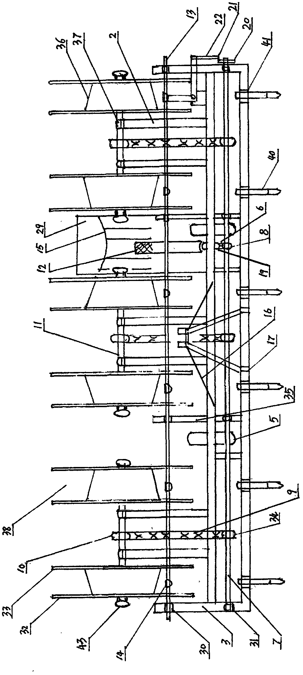
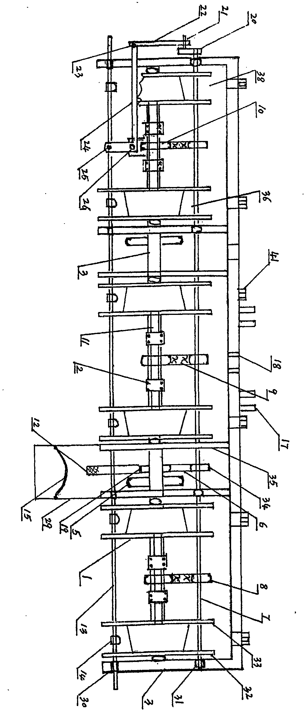
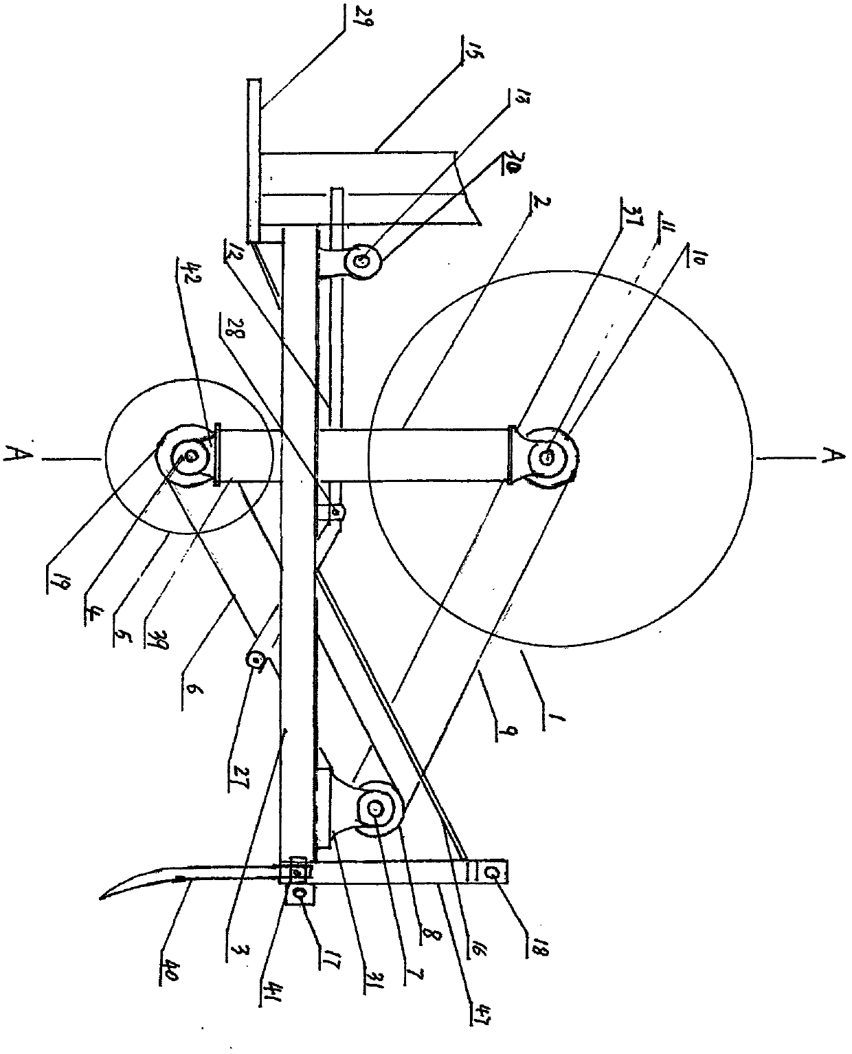
[0025] Such as Figure 1-4 The front, rear, left and right longitudinal beams (35) and diagonal stays (16) of the machine frame (3) of the waste drip irrigation belt recovery machine of the present invention shown in the present invention are mutually welded, and the middle of the front frame (3) of the machine is welded at three points Suspension frame (47), is provided with upper and lower hanging hole (17) (18) on the suspension frame (47). On the frame (3) front cross beam, the bar tooth card (41) is fixed with screws, and the bar tooth card (41) is equipped with the bar tooth (40).

[0026] Long axis (7) is adorned horizontally in front of frame (3), and four sets of long bearing blocks (31) are adorned respectively in the middle of two ends of long axis (7), and long bearing block (31) is fixed on the frame (3) with screws. Three long shaft gears (8) and a long shaft belt pulley (34) are also mounted on the long shaft (7).

[0027] Six seatposts (2) are respectively we...


PUM


Abstract

The invention relates to agricultural machinery, in particular to a waste drip tape recycling machine which can roll and pick up waste drip tapes laid on the ground, and can roll the waste drip tapes into bundles for recycling and conveyance. The waste drip tape recycling machine comprises a machine frame body, a tape feed roller body and a land wheel body. Front, back, left and right longitudinal beams and a diagonal draw bar of a machine frame of the waste drip tape recycling machine are welded with one another; a trifilar suspension frame is welded in the middle of the frame on the front side of the machine; an upper suspension hole and a lower suspension hole are formed in the trifilar suspension frame; a lever tooth clamp is fixed on a front cross beam of the frame by a screw; and a lever tooth is arranged on the lever tooth clamp; a long shaft is horizontally mounted on the front side of the frame; four sets of long bearing pedestals are respectively mounted at two ends and the middle of the long shaft; and the long bearing pedestals are fixed on the frame by screws. Six seat posts are respectively welded on a cross beam in the middle of the frame; a roll wheel bearing pedestal is fixed at a plane, facing upwards, of each seat post by a screw; a roll wheel shaft penetrates the bearing of the roll wheel bearing pedestal; an inner plate of the tape feed roller is welded at one external diameter end of a shaft sleeve; and a cone ring is welded at the middle part of the inner plate. A hole matched with a coaxial screw rod is drilled in the middle of an outer plate; and an outer plate hole is formed in the shaft screw rod in a through manner. One end of a turning plate is tightly connected to a long shaft head by a key, and the other end is welded with a turning plate pin; the two land wheel brackets are welded at the lower part of the middle section of the cross beam of the machine frame; and a land wheel bearing pedestal is tightly connected to a plane, facing downwards, of the bracket by a screw. The waste drip tape recycling machine can roll up drip tapes laid on the ground and then bundle the drip tapes laid on the ground to facilitate the loading and conveying, the working efficiency is a hundred times of the manual operation, labor is saved, and the cost is reduced.

Description

technical field [0001] The invention relates to an agricultural machine, a recycling machine for waste and old drip irrigation tapes. The machine can pick up the waste and old drip irrigation tapes laid on the ground, and roll them into round bundles for recycling and transporting. Background technique [0002] Since the emergence of drip irrigation belts for planting crops, a large number of drip irrigation belts have been laid every year to grow various crops. However, the waste drip irrigation belts in the recycling fields have been picked up manually. The efficiency of manual picking up the drip irrigation belts is low, it costs a lot of labor, increases the cost of farmers, and sometimes they can't find workers, and farmers are extremely troubled. Contents of the invention [0003] Purpose of the present invention is exactly at above-mentioned situation, a whole machinery of invention---waste and old drip irrigation belt recycling machine. [0004] The technical sche...

Claims


Application Information

Patent Timeline
Patent Type & Authority Applications(China)
IPC IPC(8): F16L1/024B65H18/08
Inventor 蒋毅蕾
Owner 蒋毅蕾
Why Eureka
Try Eureka