
Air channel heating device

An air duct heating device and technology for heating devices, which are applied in the directions of fluid heaters, lighting and heating equipment, etc., can solve the problems of complicated structure of air duct heaters, easy moisture aging of wires, troublesome temperature control, etc., so as to save labor costs, The effect of fast heating rate and improved efficiency

Inactive Publication Date: 2013-09-11
ZHENJIANG DONGFANG ENERGY SAVING EQUIP
View PDF7 Cites 5 Cited by
  • Summary
  • Abstract
  • Description
  • Claims
  • Application Information

AI Technical Summary

Problems solved by technology

As a result, the structure of the air duct heater tends to be complicated, the temperature control is more troublesome, and the wires in the device are susceptible to moisture and aging, causing potential safety hazards

Method used


Image

  • Air channel heating device
  • Air channel heating device

Examples


Embodiment Construction

[0012] The present invention will be further described below in conjunction with the accompanying drawings.

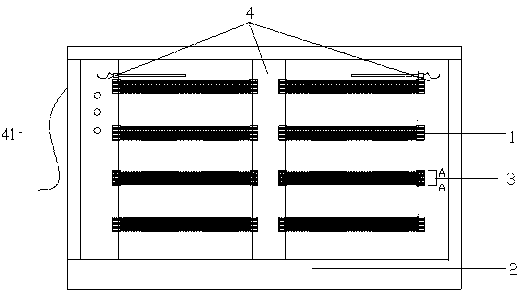
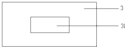
[0013] As shown in the figure, an air duct heating device includes a heater 1, and the heater 1 is fixed on the heating device bracket 2, wherein, waterproof junction boxes 3 are installed at both ends of the heater, and the back of the junction box 3 is A wire outlet 31 is provided, and the bracket is provided with a wiring cavity 4, and the junction box 3 is fixedly mounted on the outer wall of the wiring cavity 4, and the lines come out from the wire outlet 31 and pass through the wiring cavity 4, and then from the wiring cavity 4 lead out 41, except the lead out part 41 of the circuit, all others are hidden inside the frame to ensure the safety performance of the electricity.

[0014] At the same time, the heater is made of PCT thermistor, which has a fast heating speed, a large heat dissipation area, and high conversion efficiency. With the increase of the ambient...


PUM


Abstract

The invention relates to an efficient, energy-saving, safe and reliable air channel heating device which comprises heaters. The heaters are fixed onto a heating device support, waterproof junction boxes are mounted at two ends of each heater, a wire outlet is arranged on the back of each junction box, wiring cavities are arranged on the support, the junction boxes are fixedly mounted on the outer walls of the wiring cavities, and lines extend out of the wire outlets, pass through the wiring cavities and then are guided out of the wiring cavities. The air channel heating device has the advantage that except for parts which are guided out of the wiring cavities, all remaining portions of the lines are concealed inside a frame, so that the electric safety performance is guaranteed.

Description

technical field [0001] The invention relates to an air duct heating device, in particular to an auxiliary air duct heating device for air conditioning. Background technique [0002] Air duct electric heaters are used in industrial air ducts, air conditioning ducts and various industries to heat the air to increase the temperature of the output air. Generally, they are inserted into the transverse openings of the air ducts. The common feature in structure is that the electric heating tubes are supported by steel plates. In order to reduce the vibration of the electric heating tube, an over-temperature control device is installed in the junction box. In addition to the over-temperature protection, an intermodal device must be added between the fan and the heater to ensure that the electric heater starts. After the fan is started, a differential pressure device must be added before and after the heater to prevent the fan from malfunctioning. As a result, the structure of the a...

Claims


Application Information

Patent Timeline
IPC IPC(8): F24H9/18
Inventor 陈桂军
Owner ZHENJIANG DONGFANG ENERGY SAVING EQUIP
Features
  • Generate Ideas
  • Intellectual Property
  • Life Sciences
  • Materials
  • Tech Scout
  • Unparalleled Data Quality
  • Higher Quality Content
  • 60% Fewer Hallucinations
Learn More