Full-vision semi-automatic coupling platform

A semi-automatic and visual technology, applied in the field of optoelectronics, can solve problems such as difficult operation, affecting coupling efficiency and yield, and achieve the effect of convenient operation, simple structure, and prevention of misoperation

Active Publication Date: 2013-09-11
武汉钧恒科技有限公司
View PDF6 Cites 18 Cited by
  • Summary
  • Abstract
  • Description
  • Claims
  • Application Information

AI Technical Summary

Problems solved by technology

In the process of adjusting the five-dimensional adjustment frame, the eyes can only observe the first coupling object and the second coupling object through a microscope, and it is impossible or inconvenient to see objects other than the coupled figure in the process, which is very important for operating the adjustment frame It will be a potential hidden danger, because the eyes can’t see it, and the position of the adjustment frame can only be tested by proficiency and feeling. When coupling, it is necessary to adjust any five directions of the five-dimensional adjustment frame to ensure the first coupling. The relative position of the object and the second coupling object, the operation at this time is difficult to be particularly accurate, to some extent this will affect the coupling efficiency and yield

Method used


Image

  • Full-vision semi-automatic coupling platform
  • Full-vision semi-automatic coupling platform
  • Full-vision semi-automatic coupling platform

Examples


Embodiment Construction

[0036] The principles and features of the present invention are described below in conjunction with the accompanying drawings, and the examples given are only used to explain the present invention, and are not intended to limit the scope of the present invention.

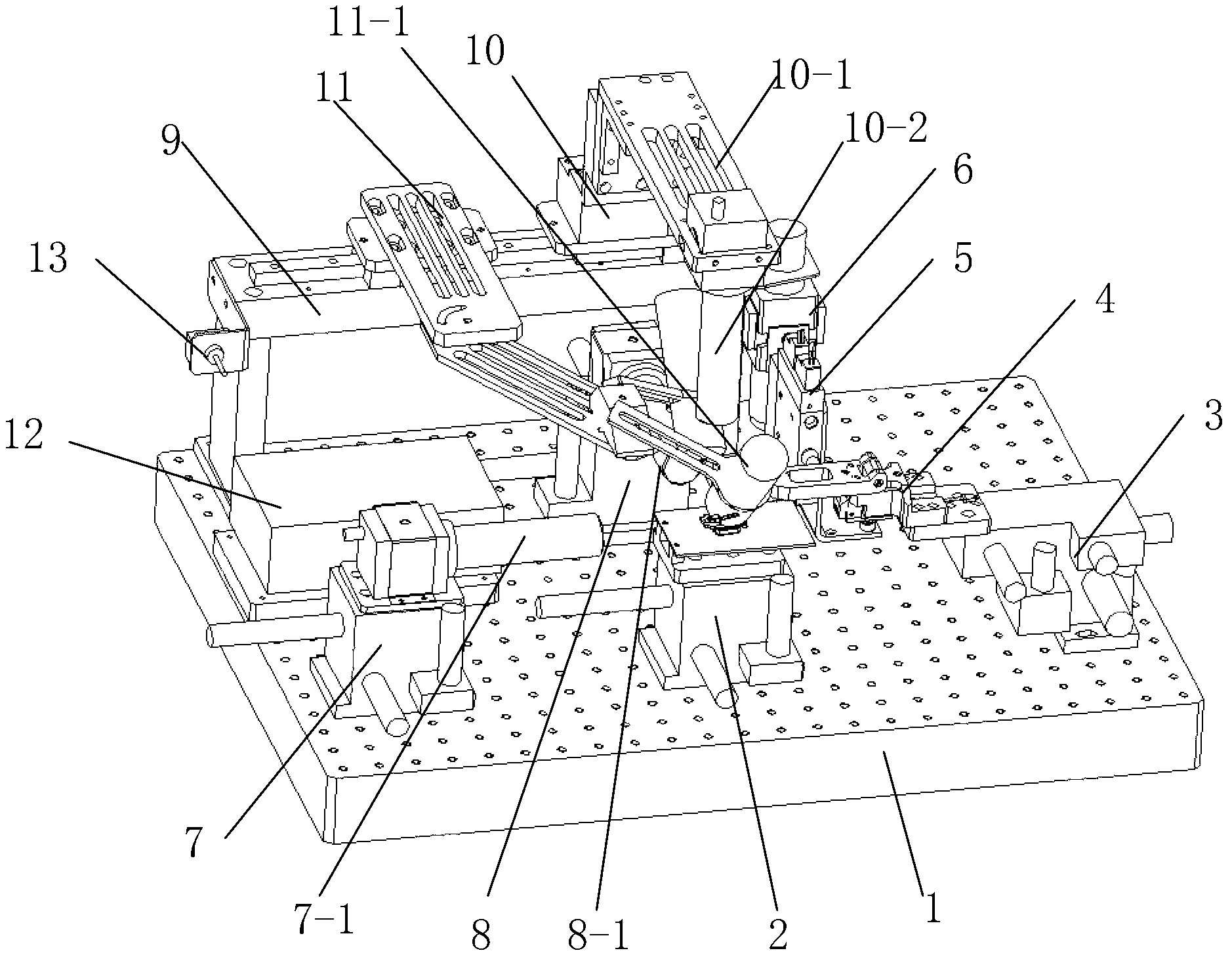
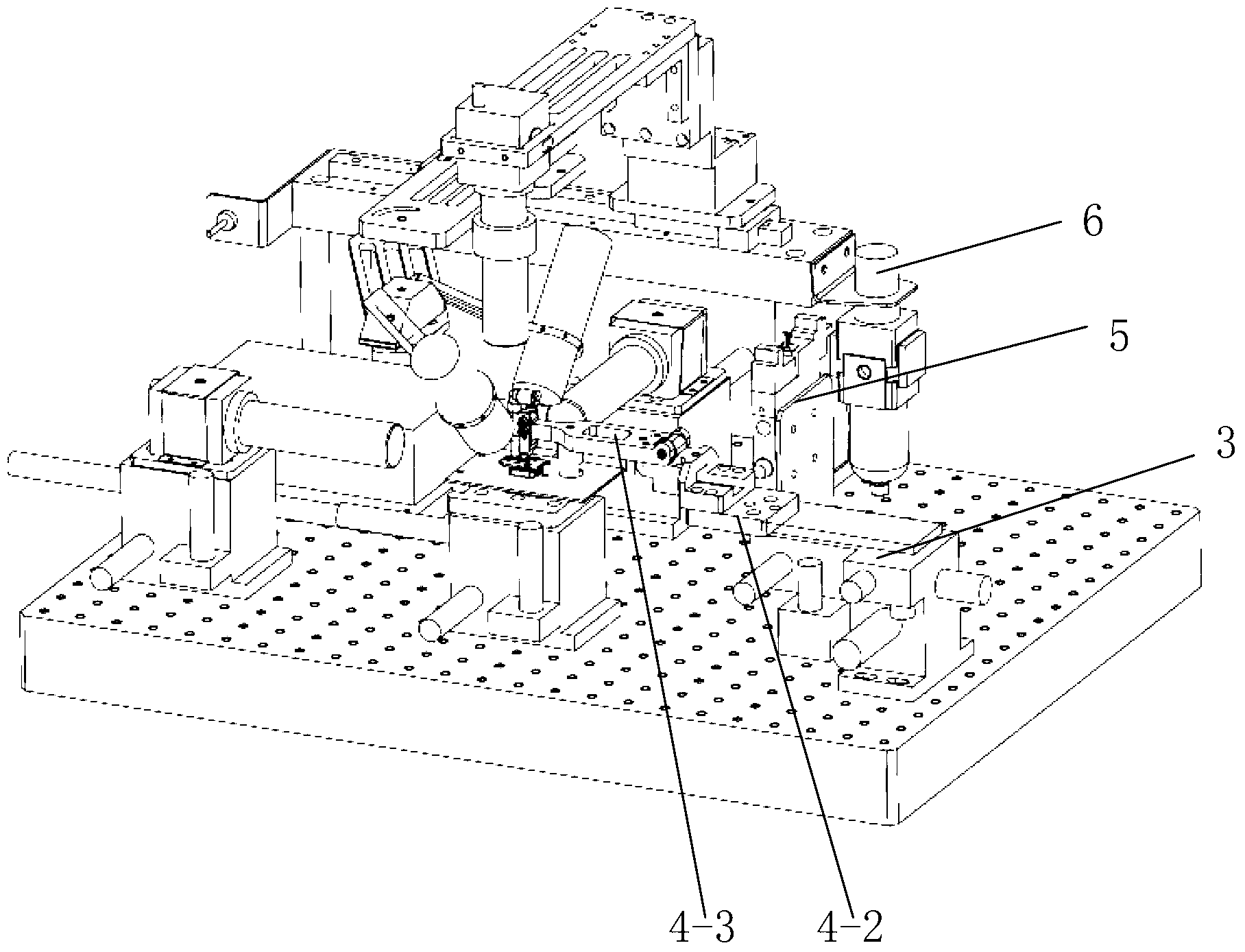
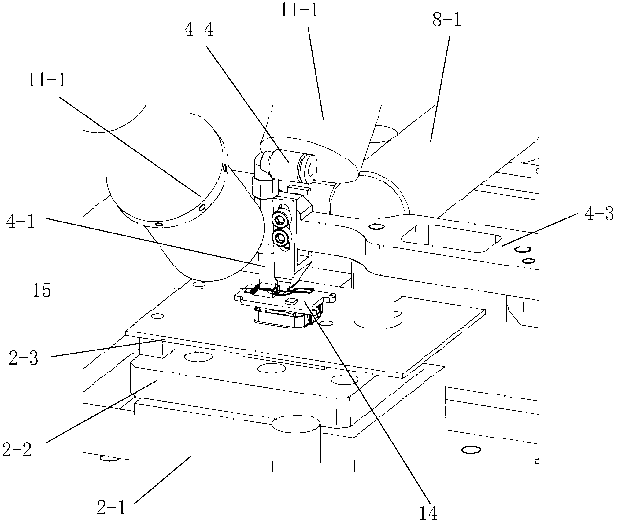
[0037] Such as figure 1 , 2As shown in and 3, a fully visual semi-automatic coupling platform includes an optical breadboard shockproof table 1, an object installation adjustment frame 2, a six-dimensional adjustment frame 3, a vacuum nozzle installation rotation mechanism 4, a compressed air filter valve 5, and a vacuum valve 6 , Side view camera installation adjustment frame 7, rear view camera installation adjustment frame 8, translation slide table 9, overlooking camera installation adjustment frame 10 and UV ultraviolet irradiation system installation frame 11;

[0038] The optical breadboard anti-vibration table 1 is a cuboid platform, and an object installation adjustment frame 2 is fixed on its upper surfac...


PUM


Abstract

The invention relates to a full-vision semi-automatic coupling platform which comprises an optical surface covering plate anti-vibration platform, an object mounting adjusting bracket, a six-dimensional adjusting bracket, a vacuum nozzle mounting rotating mechanism, a compressed air filter valve, a vacuum valve, a side-view camera mounting adjusting bracket, a rear-view camera mounting adjusting bracket, a translation slide platform, an overhead-view camera mounting adjusting bracket and a UV (ultraviolet) irradiation system mounting rack; the object mounting adjusting bracket, the six-dimensional adjusting bracket, the vacuum nozzle mounting rotating mechanism, the compressed air filter valve, the vacuum valve, the side-view camera mounting adjusting bracket, the rear-view camera mounting adjusting bracket, the translation slide platform, the overhead-view camera mounting adjusting bracket and the UV irradiation system mounting rack are fixed to the upper surface of the optical surface covering plate anti-vibration platform. The full-vision semi-automatic coupling platform has the advantages that various components are fixed onto the optical surface covering plate anti-vibration platform, so that influence of slight vibration on display parameters is prevented; one of two to-be-coupled object can be repositioned by the six-dimensional adjusting bracket, so that non-blind area adjustment is implemented; the two to-be-coupled objects can be conveniently mounted and fetched owing to the vacuum nozzle mounting rotating mechanism; the two to-be-coupled objects at opposite positions can be monitored by automatic focusing cameras from three directions, so that adjustment by the aid of the six-dimensional adjusting bracket and observation for the two to-be-coupled objects at the opposite positions can be carried out simultaneously.

Description

technical field [0001] The invention relates to the field of optoelectronics, in particular to a full-vision semi-automatic coupling platform. Background technique [0002] The existing coupling platform generally adopts the combination of five-dimensional micro-adjustment and vertical microscope observation. The five-dimensional micro-adjustment platform guarantees arbitrary adjustment of 5 degrees of freedom in space, and the coupling object is observed by the human eye through the vertical microscope during adjustment. relative position of [0003] The first coupling object and the second coupling object to be coupled, the first coupling object is fixed on the five-dimensional adjustment frame, the second coupling object is sucked on the vacuum nozzle, and the vacuum nozzle is fixed through the nozzle connecting rod; five of them The three-dimensional adjustment frame can be adjusted arbitrarily in 5 degrees of freedom in space to achieve the adjustment of the position o...

Claims


Application Information

Patent Timeline
Patent Type & Authority Applications(China)
IPC IPC(8): G01B11/00
Inventor 江亚厚华召刘鹏葛欣
Owner 武汉钧恒科技有限公司
Why Eureka
Try Eureka